
J801X Installation Manual

11
Horizontal Furnaces
WARNING:
The furnace must not be installed directly on
carpeting, tile, or any combustible material other
than wood flooring.
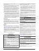
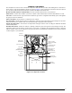
• The Ultra-Low NOx series gas furnace can be installed
horizontally (Figure 7) in an attic, basement, crawl space
or alcove. They can also be suspended from a ceiling in
a basement or utility room in either a right to left airflow
or left to right airflow as shown in Figure 8.
• Ultra-Low NOx series furnaces are shipped with the bottom
panel installed. If the furnace is installed horizontally,
remove the bottom panel from the furnace before attaching
the duct system. See Bottom Panel Removal on page
11.
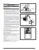
• If installing the furnace with an evaporator coil (in an
attic), it is required that a drip pan be placed under the
furnace and the evaporator coil. If the installation is on a
combustible platform (Figure 7), it is recommended that
the drip pan extend at least 12 inches past the top and
front of the furnace. NOTE: Although it is not required to
use a drip pan for heat only applications, state and local
codes may require it.
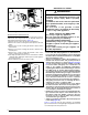
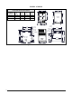
• If suspending the furnace from the ceiling, assemble a
support frame (Figure 8) using slotted iron channel and full
threaded rod. Fasten the frame together with nuts, washers,
and lockwashers. Secure the support frame to the rafters
with lag bolts. The furnace can also be suspended using
steel straps around each end of the furnace. The straps
should be attached to the furnace with sheet metal screws
and to the rafters with bolts.
• It is recommended for further reduction of fire hazard
that cement board or sheet metal be placed between the
furnace and the combustible floor and extend 12 inches
beyond the front of the door and top of the furnace.
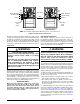
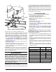
Pressure Switch Tubing
Figure 11 displays the proper routing of pressure switch
tubing for Ultra-Low NOx furnaces. The tubing connects at
one end of the pressure switch and is routed directly onto
the static tap of the inducer assembly.
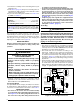
Bottom Panel Removal
The steps listed below explain the proper method for removing
the bottom panel from the furnace. See Figure 10, (page 12).
1. Remove the door from the blower compartment.
2. Disconnect the blower motor wiring harness from the
control board.
3. Remove two screws securing the blower assembly to the
furnace.
4. Carefully pull the blower assembly out thru the front of the
furnace.
5. Remove all screws securing bottom panel to bottom of
furnace and front brace.
6. Lift up and slide bottom panel out through front of furnace.
7. Reinstall the blower assembly in reverse order.
Figure 8. Horizontally Suspended in Attic
Threaded
Rod
Lag
Bolt
Nuts (x2)
Washer
and
Lockwasher
Nuts (x2)
Gas Inlet
Wood or
non-combustib
le
Platform
Type “B” Vent
Coil Plenum
Electrical Supply
Connection
Figure 7. Horizontally Installed on a Platform
Figure 9. Pressure Switch Tubing