
J801X Installation Manual


8
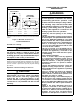
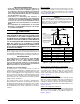
Alternate Method of Providing Air from Outside:
If acceptable under local Codes, it is permitted to provide
outside air using one opening (See NFGC). Generally,
confined spaces must have 2 openings in the space for
combustion air. One opening must be within 12 inches of
the ceiling, and the other must be within 12 inches of the
floor. However, an alternative method recently adopted by
the NFGC uses one opening within 12 inches of the top of
the space. This method may be used if it is acceptable to
the local codes.
THE FOLLOWING CONDITIONS MUST BE MET:
1. The opening must start within 12” of the top of the structure
and connect with the out of doors through vertical or
horizontal ducts or be ducted to a crawl or attic space that
connects with the out of doors.
2. The opening must have a minimum free area of 1 in
2
. per
3,000 Btu per hour of the total input rating of all equipment
located in the enclosure.
3. The free area must not be less than the sum of all the
areas of the vent connectors in the enclosure.
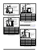
Installation In An Unconfined Space
An unconfined space is an area including all rooms not
separated by doors with a volume greater than 50 cubic feet
per 1,000 Btuh of the combined input rates of all appliances
which draw combustion air from that space.
In general, a furnace installed in an unconfined space will not
require outside air for combustion. However, in homes built for
energy efficiency (low air change rates), it may be necessary
to provide outside air to ensure adequate combustion and
venting, even though the furnace is located in an unconfined
space. See Example
EXAMPLE
A space with a water heater rated at 45,000 Btuh input
and a furnace rated at 75,000 Btuh requires a volume of
6,000 cubic feet [50 x (45 + 75) = 6,000] to be considered
unconfined. If the space has an 8 foot ceiling, the floor
area of the space must be 750 sq. ft. (6,000 / 8 = 750).
Category I Venting
This furnace is listed as a Category I vented appliance.
Category I furnaces generally operate with a slight negative
pressure (draft) and must be vented vertically or near vertical.
Additionally it is important to guard against excessive
condensation.
WARNING:
Upon completion of the furnace installation,
carefully inspect the entire flue system both
inside and outside the furnace to assure it is
properly sealed. Leaks in the flue system can
result in serious personal injury or death due
to exposure of flue products, including carbon
monoxide.
WARNING:
Venting into an unlined masonry chimney or
concrete chimney is prohibited. This may result in
improper draft and excess condensation forming
in the chimney.
• This furnace must be vented in compliance with
the current revision of the National Fuel Gas Code
(ANSI-Z223.1/NFPA54) and the instructions provided
below. Refer to the NFGC for approved vent tables.
Consult local codes for special requirements.
• In Canada, venting shall conform to the requirements
of the current (CAN/CSA B149.1) installation codes.
Consult local codes for special requirements.
• Category I furnace installations must be connected
to a factory built chimney or vent complying with a
recognized standard, or a masonry or concrete chimney
lined with a lining material acceptable to the authority
having jurisdiction.
• In the U.S., this furnace must never be vented to a
chimney or flue that services a fireplace or other
appliance designed to burn solid fuel. If the furnace
vent is to be connected to a chimney serving a fireplace,
the fireplace must be sealed off from the chimney. In
Canada, common venting with a fireplace is permitted.
Consult B149.1 and your local code authority.
• This furnace may be vented with a dedicated venting system
or common vented with other Category I appliances. Vent
connectors serving Category I and Category II furnaces
shall not be connected into any portion of mechanical
draft systems operating under positive pressure. The vent
system dimensions and material must conform to the NFGC
or local Codes. Generally, this means using Type B vent
pipe or a lined masonry chimney. When consulting the
vent sizing tables in the NFGC, the MAX capacity of the
vent must be greater than the furnaces high fire rate. The
MIN capacity must be lower than the low fire rate. If the
venting system is inappropriate for the furnace, the venting
system will need to be modified to comply with NFGC or
local codes.The minimum diameter of any vent pipe is
4 inches.
• The venting system should be designed to have the
minimum number of elbows or turns. All horizontal runs
shall slope upwards from the furnace at ¼ inch per running
foot of vent. Supports for the vent pipe must be installed
a minimum of every five feet along the vent run to ensure
no displacement after installation. Under no circumstances
shall any portion of the vent system extend into or pass
through any return air duct, supply air duct, or plenum.
• Single wall vent connectors may be used under the
limited capacity ranges found in the vent sizing tables. It
is recommended that Type B double wall vent be used for
the connector whenever possible. An existing masonry
chimney should be inspected and relined if necessary.
• Single wall metal vertical vents shall not be used for
Category I venting. The furnace vent, if metal, may
be insulated if local codes allow. Any part of the vent
system, metal vent only, not exposed to weather,
but which are exposed to temperatures below 35° F
(1° C) must be insulated to prevent condensation. All
vent insulation shall be foil backed fiberglass of one inch
minimum thickness.