
J801X Installation Manual

19
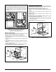
• Connect C from the primary furnace to the coil side of the
relay (using field supplied wire and 3/16” terminals).
NOTE: Make sure connections are made on opposite sides
of the coil.
• Connect R from the secondary furnace control board to
the COM side of the relay (use included red wire).
• Connect W from the secondary furnace control board to
NO side of the relay. (Use included white wire).
START-UP & ADJUSTMENTS
Pre-Start Check List
√ Verify the polarity of the connections are correct, the line
voltage power leads are securely connected and the furnace
is properly grounded.
√ Verify the thermostat wires (R, W, Y, & G) are securely
connected to the correct leads on the terminal strip of the
circuit board.
√ Verify the jumper setting (for fan speed) on the control
board. See Figure 15, (page 18).
√ Verify the gas line service pressure does not exceed 10.0
inches of W.C., and is not less than 4.5 inches W.C. for
natural gas. For LP gas the line service pressure must not
exceed 13 in. W.C., and must not be less than 11.0 in.
W.C.
√ Verify the roll-out and manual reset switch is closed. If
necessary, press the red button to reset a switch. DO NOT
install a jumper wire across a switch to defeat its function.
If a switch reopens on startup, DO NOT reset the switch
without identifying and correcting the fault condition.
√ Verify the blower door is in place, closing the door switch
in the line voltage circuit.
√ Verify the gas line has been purged and all connections
are leak free.
Start-up Procedures
Do not perform these steps until all of the checks in the
previous steps have been completed:
1. Set the thermostat to the lowest setting.
2. Turn off all electrical power to the furnace.
3. Follow the Operating Instructions on the label attached to
the furnace.
4. Set the thermostat above room temperature and verify the
Operating Sequence (page 21).
5. After 5 minutes of operation, set the thermostat below
room temperature and verify steps 9 - 10 of the Operating
Sequence.
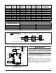
Verifying & Adjusting Input Rate
The input rate must be verified for each installation to prevent
over-firing of the furnace. NOTE: The input rate must not
exceed the rate shown on the furnace rating plate. At altitudes
above 2,000 feet, it must not exceed that on the rating plate
less 4% for each 1,000 feet. To determine the exact input
rate, perform the following procedures:
1. Shut off all other gas fired appliances.
2. Start the furnace and run it for at least 3 minutes.
3. Measure the time (in seconds) required for the gas meter
to complete one revolution.
4. Convert the time per revolution to cubic feet of gas per
hour using Table 5, (page 26).
5. Multiply the gas flow rate in cubic ft per hr by the heating
value of the gas in Btu per cubic ft to obtain the input rate
in Btuh. See Example.
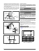
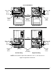
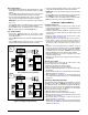
Figure 16. Single Stage Twinning
TWIN TERMINAL
BLOWER
CONTROL
BOARD
W
G
Y
C
R
FURNACE
BOARD
TWIN TERMINAL
BLOWER
CONTROL
BOARD
Expansion
Port
W
G
Y
C
R
FURNACE
BOARD
THERMOSTAT
W1
G
Y
R
AC
UNIT
W2
6-Pin Wiring
Harness
6-Pin Wiring
Harness
RELAY
COM
NO
PRIMARY FURNACE
SECONDARY FURNA
CE
Expansion
Port
Expansion
Port
Expansion
Port
C
RED
WHITE
TWIN TERMINAL
BLOWER
CONTROL
BOARD
W
G
Y
C
R
FURNACE
BOARD
TWIN TERMINAL
BLOWER
CONTROL
BOARD
Expansion
Port
W
G
Y
CR
FURNACE
BOARD
THERMOSTAT
W1
G
Y
R
W2
6-Pin Wiring
Harness
6-Pin Wiring
Harness
RELAY
COM
NO
PRIMARY FURNACE
SECONDARY FURNACE
Expansion
Port
Expansion
Port
Expansion
Port
C
RED
WHITE
SINGLE STAGE HEATING (WITH TWINNING)
TWO STAGE HEATING (WITH TWINNING)
AC
UNIT
One stage heating
• Connect the thermostat wires to the primary furnace control
board. Mount the relay on the bracket on the secondary
furnace.
• Connect W from the primary furnace to the coil side of the
relay (using field supplied wire and 3/16” terminals).
• Connect C from the primary furnace to the coil side of the
relay (using field supplied wire and 3/16” terminals).
NOTE: Make sure connections are made on opposite sides
of the coil.
• Connect R from the secondary furnace control board to
the COM side of the relay (use included red wire).
• Connect W from the secondary furnace control board to
NO side of the relay (use included white wire).
Two stage heating
• Connect the thermostat wires to the furnace control
board (except W2). Mount the relay on the bracket on the
secondary furnace.
• Connect W1 from the thermostat control to W of the primary
furnace.
• Connect W2 from the thermostat to the coil side of the
relay (using field supplied wire and 3/16” terminals).