
J801X Installation Manual

17
ELECTRICAL WIRING
WARNING:
ELECTRICAL SHOCK, FIRE OR
EXPLOSION HAZARD
Failure to follow safety warnings exactly could
result in serious injury, death or property
damage.
Improper servicing could result in dangerous
operation, serious injury, death or property
damage.
• Before servicing, disconnect all electrical
power to furnace.
• When servicing controls, label all wires prior
to disconnecting. Reconnect wires correctly.
• Verify proper operation after servicing.
• Electrical connections must be in compliance with all
applicable local codes and the current revision of the
National Electric Code (ANSI/NFPA 70).
• For Canadian installations the electrical connections and
grounding shall comply with the current Canadian Electrical
Code (CSA C22.1 and/or local codes).
Line Voltage Wiring
It is recommended that the line voltage (115 VAC) to the
furnace be supplied from a dedicated branch circuit containing
the correct fuse or circuit breaker for the furnace. See Table 2.
IMPORTANT NOTES:
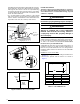
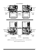
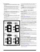
• An electrical disconnect must be installed readily
accessible from and located within sight of the furnace.
See Figure 14 or the wiring diagram label inside of
the control door. Any other wiring methods must be
acceptable to authority having jurisdiction.
• Proper line voltage polarity must be maintained in order
for the control system to operate correctly. Verify the
incoming neutral line is connected to the white wire
and the incoming “hot” line is connected to the black
wire. The furnace will not operate unless the polarity
and ground are properly connected as shown in Figure
14.
• If replacing any of the original wires supplied with the
furnace, the replacement wire must be copper wiring
and have a temperature rating of at least 105° F (40°
C). For electrical specifications, refer to the furnace
nameplate or Table 2.
Grounding
WARNING:
To minimize personal injury, the furnace cabinet
must have an uninterrupted or unbroken electrical
ground. The controls used in this furnace require
an earth ground to operate properly. Acceptable
methods include electrical wire or conduit
approved for ground service. Do not use gas
piping as an electrical ground!
Thermostat / Low Voltage Connections
• The furnace is designed to be controlled by a 24 VAC
thermostat. The thermostat’s wiring must comply with the
current provisions of the NEC (ANSI/NFPA 70) and with
applicable local codes having jurisdiction.
• The thermostat must be installed according to the
instructions supplied by the thermostat manufacturer.
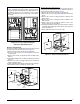
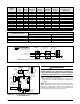
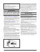
Low voltage connections (24 VAC) from the thermostat
are wired to the terminal strip on the integrated control in
the furnace. Figure 15 contains the proper connections
for heating only (two-wire) and heating/cooling (four-wire)
applications. Recommended minimum wire gauge for
thermostat wiring is shown in Table 2, (page 18).
• The thermostat should be mounted about 5 feet above the
floor on an inside wall. DO NOT install the thermostat on
an outside wall or any other location where its operation
may be adversely affected by radiant heat from fireplaces,
sunlight, or lighting fixtures, and convective heat from
warm air registers or electrical appliances. Refer to the
thermostat manufacturer’s instruction sheet for detailed
mounting information.
• The six pin terminal marked “Expansion Port” (Figure
15) is not used in the single stage furnace as shipped
from the factory. It is used for the furnace control board
to communicate to a fixed speed or variable speed high
efficiency motor that may be optionally installed. Please
contact your distributor for the proper upgrade motor kit.
Heat Anticipator
Set the heat anticipator according to the instructions supplied
by the thermostat manufacturer. To determine the heat
anticipator setting:
1. Add the current draw of the system components; or
2. Measure the current flow on the thermostat R-W circuit
after the circulating blower motor has started.
Twinning
Single stage furnaces are not supplied with a built-in twinning
capability. Other valuable features and enhancements were
made to the new control that made it necessary to remove
the twinning capability. For twinning of single stage furnaces
with fixed speed motors, a twinning kit (1010035) is available
for purchase. Please follow the instructions provided
with the kit.
If both single stage furnaces are upgraded to the fixed speed
iSEER™ blower, the twin terminal on both blower control
boards (Figure 16, (page 19)) may be used to twin the
single stage furnaces. The twinning system requires a relay
(P/N 624843) in the secondary furnace for proper twinning.
For proper twinning of fixed speed furnaces the following
criteria must be met:
• Both furnaces and motors must be the same size.
• Both motors must be on the same speed for cooling and
heating.
• Both furnaces must have a common return duct and
common supply plenum.
• Both furnaces must be the same phase and on the same
leg of power.
Furnaces equipped with variable speed iSEER™ motors
may not be twinned under any circumstances.