
Install Instructions


20
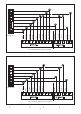
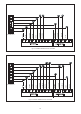
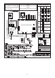
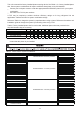
Fig.24: FACTORY DEFAULT WIRING DIAGRAM FOR J4AH6E61A1C00AA
COM
208V
240V
5
4
3
1
WHITE/BLACK
W2
CN35
22
CN33
CN4
CN5
SPEED TAPS
WHITE
GRAY
BLUE
MEDIUM LOW
LOW
MEDIUM
MEDIUM HIGH
HIGH
B
W1
Y2
GREEN
RED
YELLOW
R
C
Y1
PURPLE
BROWN
CN38
CN39
L1-A
L1-B
CN36
T2
T1
LED4
INDOOR MAIN BOARD
POWER ON
ON
NORMAL
C
CN6
G
SCHEMATIC DIAGRAM
SEE RATING PLATE FOR VOLT&HERTZ
FIELD POWER WIRING
1 2 3 4 5
54321C
N G L C
HEATER
KIT PLUG
1 2 3 4 5
N G L C
PLUG LIATE
POWER IN
6
SW6
BLACK
BLACK
RED
RED
RED
NOTES:
1: If connected to the 1-Stage controller, please short the signals Y1 and Y2.
2: Use copper wire (75℃ min) only between disconnect switch and unit .
3: To be wired in accordance with NEC and local codes.
4: If any of the original wire ,as supplied,must be replaced.Use the same
or equivalent type wire.
5: Connect R to R,G to G,Y1 to Y,etc.See outdoor instruction for details.
6: If some signal lines of CN4 and CN5 are not used,please Wrap them up
separately with cap.
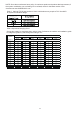
7: See airflow tables for airflow settings.
8: When need to change the transformer stage,remove the lead from “240V”
terminal and then connect the lead to “208V”terminal.
CAUTION:
NOT SUITABLE FOR USE ON SYSTEMS EXCEEDING 150V TO GROUND.
ATTENTION:
NE CONVIENT PAS AUXINSTALLATIONS DE PLUS DE 150V ALA TERRE.
24V
1 2 3 4 5
WHITE
YELLOW
BLUE
PURPLE
GREEN
N G L C
TRANSFORMER
FAN
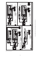
LED4 INDICATION DESCRIPTION
BROWN
W2
W1
Dh
ON
1
OFF
1
DETAILED REFERENCE
MANUAL INSTRUCTIONS
SW6-1,2
SW6-3
NORMAL
HEAT:
FAN START
RESERVED
ON
ON
ON
ON
SW6-4
1 2
ON
60K
Y1+Y2 OR WY1 OR G
1
1
2
3
2
3
4
5
*THE FACTORY DEFAULT
RESERVED
FAN SPEED
TAPS
*
*
*
BLACK BLOCK
IS BUTTON
3
ON
4
ON
4
1 2
1 2
1 2
1 2
ON
3
YELLOW/GREEN
10K RESISTANCE
10K RESISTANCE
T1:RETURN AIR TEMPERATURE SENS OR
T2:INDOOR COIL TEMP. SENSOR
YELLOW
Switch ON Position:
Color upper half to show
switch position is UP.
Switch OFF Position:
Color upper half to show
switch position is DOWN.
THE WIRING DIAGRAM SHOW IS FOR REFERENCE
ONLY,ACTUAL PRODUCT MAY VARY.