
J4AC6 Installation Manual


10
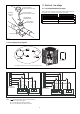
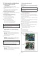
12. Electrical - high voltage
12.1 High voltage power supply
WARNING: LIVE ELECTRICAL COMPONENTS!
During installation, testing, servicing, and trouble shooting of this
product,
it may be necessary to work with live electrical
components.
Failure to follow all electrical safety precautions when exposed to
live electrical components could result in death or serious injury.
The high voltage power supply must agree with the equipment
nameplate.
Power wiring must comply with National, State and Local Codes.
Follow instructions on unit wiring diagram located on the inside of the
access panel.
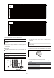
Figure 30
n
a
m
e
p
l
a
t
e
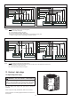
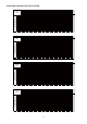
“ ” The electric auxiliary heat connection(option).
W : Electric auxiliary heat signal.
W1 : The first Electric auxiliary heat signal.
W2 : The second Electric auxiliary heat signal.
D signal is connect to the Electric auxiliary heat or the first Electric auxiliary heat.
“”: Outdoor unit signal. Only for single-stage compressor systems.
THERMOSTAT
C
GREEN
INDOOR UNIT
OUTDOOR UNIT
Y
R
G
Y
YELLOW
BLACK
BLACK
G
C
CB
R
B
RED
BLUE
Support 2H thermostat
W
D
R
PURPLE
w1
w2
WHITE
Support 3H thermostat
R
THERMOSTAT
C
GREEN
INDOOR UNIT
OUTDOOR UNIT
Y
R
G
Y
YELLOW
BLACK
BLACK
G
C
CB
R
B
RED
BLUE
W1
W2
D
PURPLE
w1
w2
WHITE
Notes:
Control Wiring for 18K-48K HP Systems
Figure 28
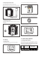
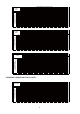
THERMOSTAT
C
GREEN
INDOOR UNIT
OUTDOOR UNIT
Y
R
G
B
YELLOW
BLACK
BLACK
G
C
CY
R
B
RED
BLUE
Support 2H thermostat
W
W
WHITE
w1
w2
WHITE
Support 3H thermostat
THERMOSTAT
C
GREEN
INDOOR UNIT
OUTDOOR UNIT
Y
R
G
B
YELLOW
BLACK
BLACK
G
C
CY
R
B
RED
BLUE
W1
W2
W
WHITE
w1
w2
WHITE
Control Wiring for 60K HP Systems
“ ” The electric auxiliary heat connection(option).
W : Electric auxiliary heat signal,connect to the Electric auxiliary heat or the first Electric auxiliary heat.
W1 : The first Electric auxiliary heat signal.
W2 : The second Electric auxiliary heat signal.
Notes:
Figure 29