
J4AC6 Installation Manual


9
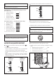
11. Electrical - low voltage
11.1 Low Voltage Maximum Wire Length
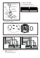
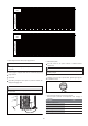
Cap
Roll ed Edge to
Capti vate Stem
Hex Headed
Val v e Sy s t em
Service Port
3/16” Hex Wrench
for Liquid Service Valve
5/16” Hex Wrench
for Sucti on Service Valve
Unit S ide
of Service
Val ve
Figure 25
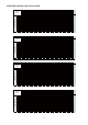
Table 6 defines the maximum total length of low voltage wiring from
the outdoor unit to the indoor unit and to the thermostat.
24 Volts - Wire size Max. wire length
18 AWG 150 Ft.
16 AWG 225 Ft.
14 AWG 300 Ft.
Table 6
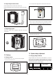
11.2 Low voltage hook-up diagrams
Low Voltage connection
must be made inside the
outdoor unit case.
Figure 26
Access
Panel
Figure 27
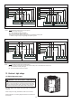
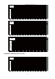
FOR TWO STAGE
HEAT THERMOSTAT
C
GREEN
INDOOR UNIT
OUTDOOR UNIT
Y
R
G
Y
YELLOW
BLACK
BLACK
G
C
C
R
B
RED
W1
W2
w1
w2
WHITE
Notes: “ ” The electric auxiliary heat connection(optional).
W : Electric auxiliary heat signal.
W1 : The first Electric auxiliary heat signal.
W2 : The second Electric auxiliary heat signal.
FOR ONE STAGE
HEAT THERMOSTAT
C
GREEN
INDOOR UNIT OUTDOOR UNIT
Y
RGY
YELLOW
BLACK
BLACK
G
C
C
R
B
RED
Control Wiring for AC Systems
W
w1 w2
WHITE