SPE series Single Channel Output DC Power Supply User Manual For product support, visit : www.owon.com.
Mar. 2022 edition V1.0.1 Copyright © LILLIPUT Company. All rights reserved. The LILLIPUT's products are under the protection of the patent rights, including ones which have already obtained the patent rights and those which are applying for. The information in this manual will replace all that in the materials published originally. The information in this manual was correct at the time of printing.
General Warranty We warrant that the product will be free from defects in materials and workmanship for a period of 2 years (1 year for accessories) from the date of purchase of the product by the original purchaser from our company. This warranty only applies to the original purchaser and is not transferable to a third party.
Table of Contents 1. General Safety Requirements ..................................................... 1 2. Safety Terms and Symbols .......................................................... 2 3. Quick Review ............................................................................... 3 3.1 Panel and Interface ............................................................................................ 3 3.1.1 Front Panel ..................................................................................
1.General Safety Requirements 1. General Safety Requirements Before use, please read the following safety precautions to avoid any possible bodily injury and to prevent this product or any other connected products from damage. To avoid any contingent danger, ensure this product is only used within the ranges specified. Only a qualified person should perform internal maintenance. To avoid Fire or Personal Injury: ◼ Use Proper Power Cord.
2.Safety Terms and Symbols 2. Safety Terms and Symbols Safety Terms Terms in this manual (The following terms may appear in this manual): Warning: Warning indicates conditions or practices that could result in injury or loss of life. Caution: Caution indicates the conditions or practices that could result in damage to this product or other property. Terms on the product. The following terms may appear on this product: Danger: Indicates an immediate hazard or injury possibility.
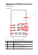
3.Quick Review 3. Quick Review 3.1 Panel and Interface 3.1.1 Front Panel 1 2 11 3 10 4 9 5 6 8 7 Figure 3-1 Front Panel Overview 1 Display Area Display user interface. 2 Current Key Set current parameters, press to move the cursor when editing parameters 3 Knob Select the main menu or change the value, function equals to the confirmation key.
3.Quick Review 5 Memory Key 5 sets of channel parameters can be stored for quick output, or long press to enter the List waveform output editing interface. 6 On/Off Key Turn on/off the channel, or long press to turn on or turn off the power-on automatic startup function. 7 Channel Output Output access of channel. Terminal 8 USP Port USB charging port (no read/write function) 5V/1A charging (without U model); Support QC2.0, QC3.0, BC1.
3.Quick Review 3.1.2 Rear Panel 1 5 3 4 2 Figure 3-2 Rear Panel Overview 1 Air Vent Air vent. 2 Power Button Turn on/off the instrument. 3 Fuse Power fuse. 4 AC Power Input AC power input interface. Jack 5 Device Port USB Update the firmware, PC software control port.
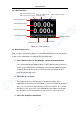
3.Quick Review 3.1.3 User Interface CV: Constant Voltage output Display cumulative CC: Constant Current output running time Actual output power Channel output status Actual voltage output Actual current output Set values of voltage Set values of O.C.P Set values of current Set values of O.V.P Figure 3-3 User Interface 3.2 General Inspection After you get a new power supply, it is recommended that you should make a check on the instrument according to the following steps: 1.
3.Quick Review If it is found that there is damage to the appearance of the instrument, or the instrument can not work normally, or fails in the performance test, please get in touch with our distributor responsible for this business or our local offices. If there is damage to the instrument caused by the transportation, please keep the package.
3.Quick Review The following steps check basic current functions with a short across the power supply's output: (1) Connect a short across (+) and (-) output terminals with an insulated test lead on this channel. Use a wire size sufficient to handle the maximum current. (2) Set the output voltage to the maximum rating on this channel. (3) Turn on the channel output. Ensure the channel you used is in Constant Current output mode.
4.Panel Operation 4. Panel Operation 4.1 Turn On/Off the Channel Output Press the On/Off key to turn on/off the channel; 4.2 Set the Output Voltage/Current In the channel setting area, press the V / I key to move the blue cursor between different positions of the voltage/current value. After pressing the output voltage/current setting value, turn the knob to change the value of the current cursor, and press the knob or press the V / I key to move the cursor.
4.Panel Operation Set values of O.V.P Set values of O.C.P 4.4 Memory key shortcut settings Press the Memory key on the front panel to store 4 sets of channel parameters M1, M2, M3, and M4 respectively for quick output. 4.4.1 Quick output To output a set of parameters from M1 to M4, follow these steps: (1) Press Memory key on front panel, the shortcut interface will display. (2) Turn the knob and a gray selection box appears. Turn the knob to move the gray selection box.
4.Panel Operation voltage protection / over current protection value. (4) Turn the knob to change the value of the current cursor, press the knob or press the V / I / OVP / OCP key to move the cursor. Set values of voltage Set values of O.V.P Set values of current Set values of O.C.P 4.5 Set List Waveform Output The user can edit and output the waveform. A set of waveforms contains 10 editable points.
4.Panel Operation move the cursor position; short press the Memory function key on the front panel to exit the parameter setting status; (5) In the non-parameter setting state, press the knob for 3 seconds to confirm, enter the "List Waveform Output Mode", and at the same time, switch back to the main interface; (6) Long press the Memory function key on the front panel for 3 seconds to exit the "List waveform editing interface". 4.5.
4.Panel Operation 4.6 Set Automatic Output at Power-on The user can turn on or turn off the "automatic output at power-on" function by pressing and holding the On/Off function key for 3 seconds. (1) The steps are as follows The user can turn on or turn off the "automatic output at power-on" function by pressing and holding the On/Off function key for 3 seconds. The steps are as follows: (2) When the "automatic output at power-on" is turned off, after power-on, the instrument is in the standby state.
5.Troubleshooting number or curve. Number Press the Display function key to set the display mode to Number. When the power supply is powered on, the default display mode is Curve. Curve Press the Display function key to set the display mode to Curve. 5. Troubleshooting 1. The instrument is powered on but no Display. ⚫ Check if the power is connected properly.
6.Appendix ⚫ If the problem still exists, please contact us for our service. 2. The output is abnormal: ⚫ Check if the output voltage is set to 0V. If so, set it to other value. ⚫ Check if the output current is set to 0A. If so, set it to other value. ⚫ When in programmable output status, check if there is any voltage/current value is set to 0. If so, set it to other value. ⚫ If the problem still exists, please contact us for our service. 6. Appendix 6.
6.Appendix Inspect the instrument as often as operating conditions require. To clean the instrument exterior, perform the following steps: Wipe the dust from the instrument surface with a soft cloth. Take care not to scratch the transparent LCD protection screen when cleaning. Disconnect power before cleaning your instrument. Clean the instrument with a damp soft cloth (not dripping with water). It is recommended to clean with soft detergent or fresh water.