Multi-Mount for Mac Pro 3.5” to 5.25” Drive Bay Converter Bracket 2.5” to 3.
OWC Multi-Mount Introduction 1 INTRODUCTION 1.1 System Requirements 1.1.1 Computer Requirements 1.1.2 Hard Drive Requirements 1.1.3 Tool Requirements 1.2 Package Contents 2 MAC PRO 667MHZ DISASSEMBLY 2.1 Mac Pro 667MHz Disassembly 3 MAC PRO 800MHZ DISASSEMBLY 3.1 Mac Pro 800MHz Disassembly 4 CABLE INSTALLATION 4.1 Cable Installation 5 OWC MULTI-MOUNT ASSEMBLY 5.1 Installing either 1 or 2 3.5” Hard Disk Drives 5.2 Installing a 2.5” Hard Disk Drive into the OWC Multi-Mount 5.3 Installing 1 or 2 2.
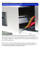
OWC Multi-Mount Chapter 6 - Bracket Installation 6 OWC MULTI-MOUNT INSTALLATION Set the optical drive assembly into the optical drive bay, there are 2 screws that line up onto a track in the bottom of the bay. Carefully route the cabling so that it’s not pinched or disconnected when fitting the carrier into the optical bay. Fully insert it so that it’s flush into the computer again.
OWC Multi-Mount Introduction Thank you for purchasing the OWC Multi-Mount system. We’re confident that it will provide years of high-performance service to you. This guide will get you up and running quickly, demonstrating how to install your own hard drives into the OWC Multi-Mount bracket system and into 2 common types of computers. Should you require additional support after reading this manual along with the helpful tips and FAQs, please see the inside back page for OWC customer support options.
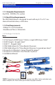
OWC Multi-Mount 1 INTRODUCTION Chapter 1 - Introduction 1.1 System Requirements 1.1.1 Computer Requirements Any 2006 - 2008 Mac Pro system 1.1.2 Hard Drive Requirements The OWC Multi-Mount is designed to work with any 3.5” or 2.5” mechanical hard disk drive, or SSD drive. 1.1.3 Tool Requirements • Phillips #1 or #2 Screwdriver • Needlenose Pliers or Hemostats 1.
OWC Multi-Mount Chapter 2 - Mac Pro 667MHz Disassembly 2 MAC PRO 667MHZ DISASSEMBLY 2.1 Mac Pro 667MHz Disassembly Begin by removing the side door on your Mac Pro. On the lower right, find the memory bay.
OWC Multi-Mount Chapter 2 - Mac Pro 667MHz Disassembly 2 MAC PRO 667MHZ DISASSEMBLY Remove the 2 memory riser cards, exposing the 2 Phillips screws shown here. Remove the 2 Phillips screws. They are long and extend through the logic board and into the back of the computer.
OWC Multi-Mount Chapter 2 - Mac Pro 667MHz Disassembly 2 MAC PRO 667MHZ DISASSEMBLY At the bottom of the memory bay, there are 2 more Phillips screws. They are a smaller head than the ones inside the memory bay that you just removed. Use a Phillips #0 screwdriver to remove the screws. There is one problem. On many machines, the screws were improperly installed.
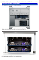
OWC Multi-Mount Chapter 2 - Mac Pro 667MHz Disassembly 2 MAC PRO 667MHZ DISASSEMBLY Make sure that the locking latch on the back right side of the Mac Pro. Then, remove all 4 of the drive bays and set them aside. Look inside the PCI Express bay at the top right of the Mac Pro. You’ll need to remove items from this location next.
OWC Multi-Mount Chapter 2 - Mac Pro 667MHz Disassembly 2 MAC PRO 667MHZ DISASSEMBLY Using a Phillips P0 screwdriver, loosen the PCI Express cover retaining plate and remove it. There is a tab at the top that the metal plate latches into, you’ll need to unscrew the 2 screws and slide the plate down out of the tab. Once the metal retaining plate is removed, remove the top PCI Express dead plate cover from the top slot as shown. Set the dead plate cover aside, you’ll be using it in a future step.
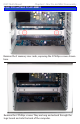
OWC Multi-Mount Chapter 2 - Mac Pro 667MHz Disassembly 2 MAC PRO 667MHZ DISASSEMBLY Remove your PCI Express video card. At the rear of the PCI Express slot, there is a small plastic tab that you need to lift up to unlock the PCI Express card. While doing this, pull gently on the card itself toward you and it will come free. Set the video card aside. Immediately to the left of the PCI slots, at the top of the logic board, you will see this Phillips screw. Using a Phillips P0 screwdriver, remove it.
OWC Multi-Mount Chapter 2 - Mac Pro 667MHz Disassembly 2 MAC PRO 667MHZ DISASSEMBLY Take the memory bay and gently move it to the right, towards the back of the computer. You’ll be able to gently shake it and it will pop loose and move just enough to expose a gap between the processor cover and the memory bay as shown. Once the memory bay is moved, you can pull out on the bottom of the processor cover on the bottom right, and gently remove it from the computer. It hinges up and to the right as shown.
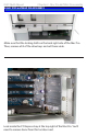
OWC Multi-Mount Chapter 2 - Mac Pro 667MHz Disassembly 2 MAC PRO 667MHZ DISASSEMBLY A view of the processor heatsinks with the cover removed. Some later model Mac Pro systems, especially 8-Core models, have a hidden Phillips screw located a the base of the fan assembly. Unscrew it.
OWC Multi-Mount Chapter 2 - Mac Pro 667MHz Disassembly 2 MAC PRO 667MHZ DISASSEMBLY Take the L shaped PCI card deadplate you removed on page #7. Starting at the top of the fan shroud, work the short end of the bracket into the gap at the back of the Mac Pro, as shown above. Once the bracket is inserted, you can use it as a hook to help pull the fan assembly out of the Mac Pro. Place the bracket at the bottom left like shown here. Start putting gentle force on the bracket, pulling on it. Then....
OWC Multi-Mount Chapter 3 - Mac Pro 800MHz Disassembly 3 MAC PRO 800MHZ DISASSEMBLY 3.1 System Requirements Begin by removing the side door on your Mac Pro. Make sure that the locking latch on the back right side of the Mac Pro. Then, remove all 4 of the drive bays and set them aside.
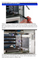
OWC Multi-Mount Chapter 3 - Mac Pro 800MHz Disassembly 3 MAC PRO 800MHZ DISASSEMBLY Immediately to the left of the PCI slots, at the top of the logic board, you will see this Phillips screw. Using a Phillips P0 screwdriver, remove it. Remove the cover over the processors by pulling on it. There are magnets securing the cover in place.
OWC Multi-Mount Chapter 3 - Mac Pro 800MHz Disassembly 3 MAC PRO 800MHZ DISASSEMBLY Remove the Phillips screw from the base of the fan assembly, located at the bottom left of the processor heatsinks. Using your right hand, wiggle, tug, and pull the entire fan assembly out of the computer. It attaches to the logic board via a connector that you don’t need to worry about disconnecting, it’s a pressure fit.
OWC Multi-Mount 4 CABLE INSTALLATION Chapter 4 - Cable Installation 4.1 Cable Installation Now that you have fully exposed the logic board, look for the 2 SATA ports, circled here. Insert the L shaped SATA cable into the top SATA port on the logic board.
OWC Multi-Mount 4 CABLE INSTALLATION Chapter 4 - Cable Installation Insert the straight SATA cable into the bottom SATA port on the logic board. Grasp the optical bay with your fingers and pull straight out. The drive carrier may require a bit of shaking to dislodge it from it’s mounts but it will come right out. Disconnect the power and ATA cables from the back of the existing optical drive and set the carrier on a work surface in front of you.
OWC Multi-Mount 4 CABLE INSTALLATION Chapter 4 - Cable Installation Start routing the SATA cables that you have already attached to the logic board up through the corner of the optical bay, following the existing wires. Here you see the proper routing of one of the SATA cables, behind drive tray #1’s logic board connector. Make very sure you have the cables all the way tucked in behind the connector before proceeding.
OWC Multi-Mount 5 OWC MULTI-MOUNT ASSEMBLY Chapter 5 - Bracket Assembly 5.1 Installing either 1 or 2 3.5” Hard Disk Drives Begin by positioning the bottom 3.5” hard disk drive with the connection ports facing away from you, and then pick up the OWC MultiMount 3.5” drive bracket that has the white OWC Multi-Mount 3.5” silkscreening on it. Place the OWC Multi-Mount onto the bottom 3.5” hard disk drive using the center Phillips screw - coarse thread - and don’t tighten it all the way yet. Leave it loose.
OWC Multi-Mount 5 OWC MULTI-MOUNT ASSEMBLY Chapter 5 - Bracket Assembly Once you have the right bracket installed, rotate the hard drive and attach the left side bracket using the same method as step 1. You also can add a 2.5” hard disk drive using the OWC 2.5” Multi-Mount. See the next chapter if you are wanting to install a mixed environment of drive mechanisms. The OWC 3.5” Multi-Mount assembly is ready to install into your system.
OWC Multi-Mount Chapter 5 - Bracket Assembly 5 OWC MULTI-MOUNT ASSEMBLY 5.2 Installing a 2.5” Hard Disk Drive To install a 2.5” Drive into the OWC Multi-Mount, place the 2.5” drive mechanism on the table in front of you, with the interface connection to the right side. Take the OWC Multi-Mount 2.5” drive bracket that has the white OWC silkscreen on it, and attach it to the drive mechanism as shown above, with the portion of the bracket that has the OWC logo extended off of the drive to the left.
OWC Multi-Mount Chapter 5 - Bracket Assembly 5 OWC MULTI-MOUNT ASSEMBLY 5.3 Installing 1 or 2 2.5” Hard Disk Drives Once you have the 2.5” OWC Multi-mount attached to the 2.5” hard disk drive, you can install up to (2) 2.5” drives onto the 3.5” OWC Multi-Mount bracket. In the above picture you see an arrow pointing towards the extended portion of the 2.5” OWC Multi-Mount bracket. That would be the front of the drive, the 2.
OWC Multi-Mount 5 OWC MULTI-MOUNT ASSEMBLY Chapter 5 - Bracket Assembly Here you see a completed assembly comprised of one set of 3.5” OWC Multi-Mount drive brackets, and two sets of 2.5” OWC Multi-Mounts, all assembled into one unit. The 2.5” OWC Multi-Mount is attached to the 3.5” OWC Multi-Mount using 6 of the fine thread Phillips screws included with the mount - 3 per side, 6 total per drive bracket assembly.
OWC Multi-Mount Chapter 5 - Bracket Assembly 5 OWC MULTI-MOUNT ASSEMBLY 5.4 Installing 1 2.5” Hard Disk Drive and 1 3.5” Hard Disk Drive into the OWC Multi-Mount This is a completed assembly comprised of one set of 3.5” OWC MultiMount drive brackets, and one set of 2.5” OWC Multi-Mount, all assembled into one unit. Be sure to orient the bracket so that the SATA ports both point towards the rear of the Multi-Mount.
OWC Multi-Mount Chapter 6 - Bracket Installation 6 OWC MULTI-MOUNT INSTALLATION 6.1 Installing the OWC Multi-Mount into a Mac Pro Attach the OWC Multi-Mount using the 4 screws that come already installed in the Mac Pro’s optical drive bracket.
OWC Multi-Mount Chapter 6 - Bracket Installation 6 OWC MULTI-MOUNT INSTALLATION Reinsert the fan module into the computer, sliding it on it’s base track and then reinserting it’s Phillips screw into the logic board. Take careful note of the location of the red SATA cable in this picture - you will need to make sure that the cable is not behind the mounting bracket when you tighten the screw. Mac Pro 667MHz Owners; Turn to the end of Chapter 2 and work backwards to complete reassembly of your Mac Pro.
OWC Multi-Mount 7 TROUBLESHOOTING & TIPS Chapter 7 - Troubleshooting & Tips 7.1 Troubleshooting Having problems installing? Go back and examine the steps and photographs. Most fit issues can be traced to missing a step or a screw. Double check that your brackets are facing the correct direction and that you are not orienting the drive backwards. You want to be sure that the SATA ports are pointing in the right direction for your case installation. 7.
OWC Multi-Mount 8 APPENDIX Chapter 8 - Appendix 8.1 FAQ Q: How do I format my storage solution? A: OWC has detailed instructions online for most popular operating systems, located at: http://eshop.macsales.com/tech_center/fwhdd.
OWC Multi-Mount 9 CUSTOMER SERVICE Chapter 9 - Customer Service 9.1 Before Contacting Customer Service •Read this manual and review Chapter 4: Troubleshooting & Tips. •Try to confirm the problem is with the hard drive. If you have a second computer, move the enclosure to that system and verify that the solution does not function with that machine. •Visit our tech center for more support suggestions, including FAQs. http://eshop.macsales.com/tech_center/index.
Copyrights: Copyright © 2010 Other World Computing, Inc. All rights reserved. OWC is a registered trademark of Other World Computing. Other World Computing and Mercury Elite-AL Pro are trademarks of Other World Computing. Other marks may be the trademark or registered trademark property of their respective owners.