
Technical Specs

DESI-BOK100_9103-en-C.doc
6
5.3. Connecting the cables
▪ Disconnect the power from the equipment whenever you manipulate it.
▪ Allow sufficient cabling to enable the removal of the equipment.
▪ Place a 2A fuse in the Vin positive cable.
▪ Ensure cables are not damaged or rubbing against sharp objects.
▪ The antennas should have an unobstructed view. GPS should have unobstructed view of the sky. Antennas should not be shielded from
satellite signals by metal objects or other impenetrable materials.
▪ The antennas have to be safe from damage during normal vehicle or installation operation and maintenance. Choose a location with
access both above and below the antenna-mounting surface. This access is required for installing fasteners and for routing the antenna
cable.
▪ Separate GSM and GPS antennas when possible.
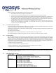
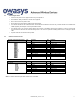
5.4. Machine Connector Pin-Out
Machine Connector: Micro-Fit 24
pin
Pin
Function
Pin
Function
12 24
1 13
12
GND
24
Vin
11
ON/OFF
23
V_OUT (4V5)
10
TXD-4
22
RXD-4
9
TXD-5 / RTS-4
21
RXD-5 / CTS-4
8
TXD-1
20
RXD-1
7
RS485A
19
RS485B
6
DIO-0 / AIN0
18
DIO-1 / AIN1
5
DIO-2 / AIN2 // CANL2*
17
DIO-3 / AIN3
4
DIO-4 // CANH2*
16
DIO-5 / K LINE2
3
DIO-6 /i-Button
15
DIO-7 / LIN / K LINE1
2
DIO-8 HS
14
DIO-9 HS
1
CANL1
13
CANH1
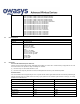
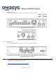
Optional Exp Connector: Micro-
Fit 14 pin
Pin
Function
Pin
Function
7 14
1 8
7
CAN4H
14
CAN4L
6
CAN3H
13
CAN3L
5
SPM
12
SPP
4
MCN
11
MCP
3
2NDRS485A
10
2NDRS485B
2
GND
9
DIN10
1
DIN11
8
DIN12
*Note: For owa450 with CAN2 option DIO2 and DIO4 are not available.