User´s Manual CI-8060
Acknowledgements EPSON is a Trademark of Seiko Epson Corporation. IBM is a Trademark of International Business Machines Corporation. ProPrinter is a Trademark of International Business Machines Corporation. A Publication of Output Solutions GmbH Bavierstraße 1 D-40699 Erkrath Federal Republic of Germany January 2002 Great care has been taken to ensure that the information in this handbook is accurate and complete.
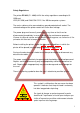
Safety Regulations The printer PP 806 (CI - 8060) fulfills the safety regulations according to UL 1950 and VDE (IEC 950) and CNA/CSA C22.2 / No. 950 for computer systems. The mains cable must be connected to a ground protected wall-socket. The selected voltage of the printer needs to fit to the local voltage. The power plug must be easily accessible at any time so that it can be disconnected immediately in case of danger or for maintenance purposes.
Safety Regulations Electromagnetic Compatibility We certify that the equipment at issue, Type: Printer PP 806 (CI - 8060) corresponds to the law regulations ruling electromagnetic compatibility of appliances (89/336/EWG) and, therefore, fulfills the requirements for conformity marking with the CE-sign.
Safety Regulations Shielded interface cables should be used with this unit to ensure compliance with Class B limits. Changes and modifications not explicitly allowed by the equipment's manufacturer could void the user's authority to operate the equipment. Changes et modifications pas expressément approuvés par le producteur peuvent dévaluer l'autorité d'opérer l'équipement. Operating Environment Avoid installing the printer where it is exposed to moisture or heat (eg. direct sunlight).
Safety Regulations Power On/Off - Lever To switch the printer on or off push the Power On/Off - Lever always down. Power - On Power Off Lifting the On/Off - Lever to the zero position won’t switch off the printer. Push the On/Off - Lever always down for switching on or off.
Table of Contents Preface . . . . . . . . . . . . . . . . . . . . . . . . . . . . . . . . . . . . . . . . . . . . . . . . . . . . . . XI About this manual . . . . . . . . . . . . . . . . . . . . . . . . . . . . . . . . . . . . . . . . . . . . . . XI 1.Getting started . . . . . . . . . . . . . . . . . . . . . . . . . . . . . . . . . . . . . . . . . . . . . 1-1 1.1 Unpacking . . . . . . . . . . . . . . . . . . . . . . . . . . . . . . . . . . . . . . . . . . . . . . . 1-1 1.
Table of contents 2. Printer Operation . . . . . . . . . . . . . . . . . . . . . . . . . . . . . . . . . . . . . . . . . 2-1 2.1 Operator Panel . . . . . . . . . . . . . . . . . . . . . . . . . . . . . . . . . . . . . . . . . . . 2-1 2.2 Function Keys . . . . . . . . . . . . . . . . . . . . . . . . . . . . . . . . . . . . . . . . . . . . 2-2 2.2.1 Ready Mode . . . . . . . . . . . . . . . . . . . . . . . . . . . . . . . . . . . . . . . . . 2-4 2.2.2 Local Mode . . . . . . . . . . . . . . . . . . . . .
Table of Contents 3.5.17 3.5.18 3.5.19 3.5.20 3.5.21 3.5.22 Tear Off Mode . . . . . . . . . . . . . . . . . . . . . . . . . . . . . . . . . . . . . Interface . . . . . . . . . . . . . . . . . . . . . . . . . . . . . . . . . . . . . . . . . Language . . . . . . . . . . . . . . . . . . . . . . . . . . . . . . . . . . . . . . . . Recall Factory . . . . . . . . . . . . . . . . . . . . . . . . . . . . . . . . . . . . . Program Update . . . . . . . . . . . . . . . . . . . . . . . . . . . . . . . . . . .
Table of contents 5 Maintenance . . . . . . . . . . . . . . . . . . . . . . . . . . . . . . . . . . . . . . . . . . . . . 5-1 S Preferred Materials . . . . . . . . . . . . . . . . . . . . . . . . . . . . . . . . . . . . . . 5-1 5.1 Cleaning the Platen and Surrounding Areas . . . . . . . . . . . . . . . . . . . . . 5-1 S PRINT MENU . . . . . . . . . . . . . . . . . . . . . . . . . . . . . . . . . . . . . . . . . . . 5-1 5.2 Cleaning Procedure . . . . . . . . . . . . . . . . . . . . . . . . . . . . . .
Table of Contents 7 7.1 7.2 Options . . . . . . . . . . . . . . . . . . . . . . . . . . . . . . . . . . . . . . . . . . . . . . . . Printer Stand . . . . . . . . . . . . . . . . . . . . . . . . . . . . . . . . . . . . . . . . . . . . . Automatic Sheet Feeder Cassettes (ASF) . . . . . . . . . . . . . . . . . . . . . . 7.2.1 Checking the Delivery Consignment . . . . . . . . . . . . . . . . . . . . . 7.2.2 Prepare the ASF Cassette . . . . . . . . . . . . . . . . . . . . . . . . . . . . . 7.2.
Table of contents Appendices System Interface Descriptions . . . . . . . . . . . . . . . . . . . . . . . . . . 1 Serial Interface RS 232C / RS 422 . . . . . . . . . . . . . . . . . . . . . . . . . . 1.1 Interface Characteristics . . . . . . . . . . . . . . . . . . . . . . . . . . . . . . 1.2 Transmission Protocols and Connection Diagrams . . . . . . . . . . 1.2.1 DTR - Ready / Busy . . . . . . . . . . . . . . . . . . . . . . . . . . . . . . 1.2.2 XON / OXOFF . . . . . . . . . . . . . . . . . . . . . . . .
Table of Contents Preface About this Manual This manual covers the printer in combination with an interface module (Personality Module). The Personality Module (PM) is an integral part of the printer, and the type of PM used significantly influences the behaviour or operation of the printer. The structure of this manual is such that the operator is led step-by-step through the various procedures.
Preface 4. Description of the Individual Menu Items In this chapter you will find a detail explanations of individual menu items. 5. Maintenance This chapter shows how to clean the printer and how to replace the print head. 6. Trouble Shooting and Diagnostics suggests how to identify and correct simple problems. 7. Options This is a brief description of all available options. Supplements enclosed in the packaging of options may be inserted here. 8.
Preface D. Control Codes Quick reference for IBM Proprinter and IBM Proprinter AGM (4207, 4208 XL 24) Emulation. E. Control Codes Quick reference for EPSOM LQ 2550 and ESC/P2 Emulation. F. Control Codes Quick reference for Barcode programming. G.
Preface Conventions Used in this Guide The following conventions are used: Bold Headlines and important information. Note: Contains special advice to facilitate handling. Caution: Contains important information to prevent damage of the equipment. [ENTER] Key functions are always depicted in brackets or you will find the symbol of the key e.g .
1. Getting Started 1.1 Unpacking Check each item against the check list detailed below. Contact your supplier immediately if any item is missing or damaged. The package contains the printer and a box (1): Note: Save all packing material and boxes for future transportation of the printer. The box (1) contains an additional smaller box (2) with the interface (Personality Module, PM).
Getting Started The box (1) contains the following: First shelf: S Ribbon Cassette (4) S Quick Reference Guide (5) S CD-ROM (6) S Power cord (7) Take the parts (4) to (7) out of the package (1) and open the second cover (3). Second shelf: Take out the Paper Insertion Guide (8) and the Manual Sheet Feeder (9). Lowest shelf: Turn the box (1) and remove the smaller PM box (2) (see page before).
Getting Started Check each item against the check list detailed below. Contact your supplier immediately if any item is missing or damaged.
Getting Started 1.2 Requirements to the location of the printer Environmental Conditions S S S Install the printer in an area away from any heat source, air conditioner, or strong airflow. Avoid installing the printer where it is exposed to moisture or heat (eg. direct sunlight). Avoid installing the printer in a dusty or humid environment. Preconditions for Installation S S Place the printer on the stand or a table.
Getting Started 1.3 Remove Transport Lock Remove all transport locks (4) of the tractor cassettes. Open the rear cover (2) by pressing the two locking buttons (1) and swivel the rear cover backwards. 3 Remove the transport lock (3) for the print head carriage.
Getting Started Re-packing Information To ensure maximum protection when transporting the printer, always: S S S S S Remove any installed paper handling option. Remove the mains cable. Remove the ribbon cassette. Reposition the transport lock. Pack the printer in its original packing material and ship in its original package. 1.4 Installing the Personality Module (PM) The printer is only operational when an interface is installed, called a Personality Module (PM).
Getting Started 1.5 S S S Mains Connection and Power On Connect the printer to the mains using the power cord. First connect the cable to the power cord socket and then to the mains. Do not plug into the same wall outlet other equipment besides the printer such as coffee machines, copy machines, or air conditioners. The power On/Off lever switches the printer‘s power supply ON or OFF. Note: Press the lever always down.
Getting Started 1.6 Ribbon Installation Note: It is recommended to use only original ribbon cassettes supplied by the printer manufacturer. Using other ribbons will void your warranty. The following procedure describes how the ribbon cassette is installed into the printer for the very first time. Lateron chapter 1.7 Replacing the Ribbon Cassette is applicable. Note: The prind head must be always in the park posirtion.
Getting Started S Slide the ribbon cassette (3) into the printer. S Close the rear cover (2) and lock the printer (Press 1.7 Replacing the Ribbon Cassette Caution: S S S S S S ). The print head may be very hot immediately after printing! To install the ribbon, the printer must be powered on. Put the printer into the Local Mode. (Press ). Unlock the rear cover (2). (Press ). Open the rear cover (2) of the printer by pressing simultaneously the two lokking buttons, see picture on page before.
Getting Started 1.8 Paper Loading There are three possibilities for paper feeding: S Fanfold paper with the two tractor cassettes; S Single sheets through the manual paper path; S With the automatic sheet feeder cassettes (ASF-Cassettes, optional). For further information please refer to chapter 7.2 ASF Cassettes. 1.8.
Getting Started 1.8.2 Fanfold Paper Feeding Note: Ensure that all transport locks are removed. S S The printer has to be placed at the front edge of the table or on the printer stand as described in chapter 7.1 Printer Stand. Remove the manual sheet feeder(1) S Insert the lower (2) or the upper (3) tractor cassette, or both. S Step 1: Adjust the tractors roughly to the paper width. Note: The left tractor is in a fix position.
Getting Started S Step 2: Open the tractor covers, insert the paper, and close the tractor covers. S Move the right tractor (1) until the paper is straight but not too tight. S Insert the Manual Sheet Feeder (4) and initiate a test printout, see chapter 1.9 Test Printouts to check the margins.
Getting Started 1.8.3 Manual Sheet Feeding S Insert the Manual Sheet Feeder (1) and connect it to the paper insertion guide: 1 S S Select the paper source MANUAL using either the menu function or by means of the corresponding command in your application program, see chapter 1.8.1 Paper Source Selection. Initiate a printout, see chapter 1.9 Test Printouts.
Getting Started 1.9 Test Printouts There are four test printouts available. S PRINT MENU shows the current settings of all parameters and the contents of the macros. S CONFIGURATION lists all available fonts and indicates the page counter value. S PRINT LETTER produces a standard letter (ECMA-132) which can be used for measuring the printer’s throughput. S PRINT LINES shows a pattern of all printable characters. Use this to check the print qiality as well as the top and left margin.
Getting Started Sample: PRINT MENU PRINT OUT FW-VERSION 20xxxxxx HW-VERSION 29xxxxxx FPGA 4.7 PAGE COUNT 50 INTERFACE I/F TYPE WORD LENGTH BAUD-RATE PARITY BIT PROTOCOL DSR/CTS MODE I/F BUFFER MENU ACCESS PARALL./RS232 8 BIT 9600 BIT/S EVEN DTR IGNOR. DSR+CTS 64 KBYTE FULL ACCESS CURRENT SETTINGS MACRO 1* MACRO 2 MACRO 3 MACRO 4 PAPER SOURCE TRACTOR LOWER TRACTOR LOWER TRACTOR LOWER TRACTOR LOWER TRACTOR LOWER PAPER EXIT PATH BATCH BATCH BATCH BATCH BATCH BATCH CAPACITY PRINT POS. ADJ. TRACT.L.
Getting Started Sample: CONFIGURATION CONFIGURATION FW-VERSION C031 ISO 8859/1 C062 IBM SET 2 C100 CODE PAGES EE CO32 ISO 8859/15 C063 IBM CODE PAGE C101 CODE PAGES EE2 C061 IBM SET 1 C071 EPSON EXT. GCT DATA SAN SERIF COURIER SCRIPT OCR A ORATOR ROMAN SAN SERIF PRESTIGE SCRIPT ORATOR-C ORATOR ROMAN COURIER PRESTIGE OCR B ORATOR-C DATA LARGE NLQ LQ NLQ LQ NLQ ZEICHENSATZ : 202xxxxx PAGE COUNT NLQ LQ NLQ NQ NLQ LQ EPSON EXT. GCT 126 LQ NLQ LQ LQ LQ LQ 1: U.S.A.
Getting Started Sample: PRINT LETTER Eilzustellung Norddeutsche Farbwerke KG Herrn Dr. Grauert Große Elbstraße 64 2000 Hamburg 4 Org. III 5/37 17.04.75 Volkmann H-A 4 34 Vordruckgestaltung für den allgemeinen Schriftverkehr, für das Bestell- und Rechnungswesen 22.04.75 E i l t Sehr geehrter Herr Dr. Grauert, Sie können das Schreiben der Briefe, Bestellungen, Rechnungen usw.
Getting Started Sample: PRINT LINES ABCDEFGHIJKLMNOPQRSTUVWXYZabcdefghijklmnopqrstuvwxyz0123456789!§ §ABCDEFGHIJKLMNOPQRSTUVWXYZabcdefghijklmnopqrstuvwxyz0123456789! !§ABCDEFGHIJKLMNOPQRSTUVWXYZabcdefghijklmnopqrstuvwxyz0123456789 9!§ABCDEFGHIJKLMNOPQRSTUVWXYZabcdefghijklmnopqrstuvwxyz012345678 89!§ABCDEFGHIJKLMNOPQRSTUVWXYZabcdefghijklmnopqrstuvwxyz01234567 789!§ABCDEFGHIJKLMNOPQRSTUVWXYZabcdefghijklmnopqrstuvwxyz0123456 6789!§ABCDEFGHIJKLMNOPQRSTUVWXYZabcdefghijklmnopqrstuvwxyz012345 56789!§ABCDEFGHIJKLM
Getting Started 1.10 Connecting to the System Parallel/Serial Interface S Switch the printer and the computer OFF. S Connect the interface cable coming from the computer to the printer's parallel (1) or serial (2) port.
Getting Started 1.12 Emulation Selection The following emulations are included in the PM Ser/Par: S EPSON LQ / ESC/P2 in Macro 1 (Default) S IBM ProPrinter XL 24 in Macro 2 S IBM ProPrinter XL 24 AGM in Macro 3 S EPSON LQ / ESC/P2 in Macro 4 To change from one emulation to another, follow the procedure below. The example shows the keys to press along with the display information for a change from EPSON LQ / ESC/P2 in Macro 1 to IBM ProPrinter in Macro 2. Switch the printer ON.
2. Printer Operation Mos of the printer functions could be executed via operator panel as well as via software commands from the host system. Some functions become only effective with Operator Panel keys, for example: locking/unlocking the printer. 2.1 Operator Panel The Operator Panel S controls the set-up for communication with the host computer; S controls various parameter settings; S allows manual control of the paper handling; S gives information about the printer's status.
Printer Operating 2.2 Function Keys If the printer is powered on, the display shows READY 1 ELQ and the green LED lights. The printer is in the Ready Mode. The printer works in two different modes, the Ready Mode and the Local Mode. To put the printer into the Local Mode, press the Online / Offline-key . Ready Mode In this mode only the red [Online/Offline] key is active and the green LED lights. By pressing the key the printer changes into the Local Mode and the green Online-LED extinguishes.
Printer Operating KEY DISPLAY [Form Feed] EJECT PAPER 1) INSERT MANUAL1) INSERT TRACTOR1) INSERT TRACTOR U(pper)1) INSERT TRACTOR L(ower)1) PAPER TEAR OFF PAPER PARK FORM FEED REV. FORM FEED [Macro Selection] MACRO 1 MACRO 2 MACRO 3 MACRO 4 [Lock Cover/ Unlock Cover] LOCK COVER UNLOCK COVER UNLOCK COVER/ PH Note: PH means Print Head The following keys have only one function: KEY FUNCTION [Online / Offline] After pressing this key, the printer enters the ONLINE or OFFLINE mode.
Printer Operating KEY [Cursor] FUNCTION As soon as the menu mode has been activated, the four keys can only be used as cursor keys to move within the menu tree. Up, Down, Right, and Left Key 2.2.1 READY Mode In the READY mode only the [Online/Offline] key has a function: After pressing that key the printer enters the LOCAL mode. 2.2.2 LOCAL Mode All keys have at least one function.
Printer Operating Single sheet: S only form feed function. Either the form is fed into print position or is ejected. Fanfold Paper: 1) Paper is in Park Position S paper is fed into print position. 2) Paper is in Print Position S paper is fed to the tear off position. S paper is fed into park position.
Printer Operating 2.3 Liquid Crystal Display (LCD) The LCD indicator gives information about the status of the printer. In general it can be distinguished between: S S ONLINE messages OFFLINE messages Note: Messages which exceed the 16 character display, e.g. error messages, are horizontally scrolled.
Printer Operating And then, the message is scrolled: - CHECK RIBBON..... Insert the ribbon cassette, seechapter 1.6 Ribbon Installation and press The display shows: . LOCKING COVER After the locking procedure the display shows: LOCKED In this state it is possible to use all keys. The printer is still in the OFFLINE Mode due to the previous error condition is cleared now. Press and the printer switches into the ONLINE Mode.
Printer Operating 2.4 Menu Mode All selectable features are accessible via the operator panel and combined in the printer MENU. This feature provides: S easy configuration (language, etc.
Printer Operating 2.4.1 To Activate the Menu To activate the menu please follow the next steps: Press : The printer changes from the READY mode into the LOCAL mode. The display shows: LOCAL Note: 1 ELQ The second term identifies the active macro and the emulation. Press : Now, the printer enters the menu mode at the first level of the menu tree.
Printer Operating Press : The display shows: » PAPER SOURCE º Press : Now, you are at the third level. The display shows: » TRACTOR L/U r The default value for PAPER SOURCE is TRACTOR L/U (lower or upper). At the lowest level, parameters and values, the asterisk (*) to the right indicates the actual selection. To change this parameter into paper source MANUAL, press twice . The display shows: » MANUAL Press to confirm the choice: The display shows: » MANUAL To quit the menu mode press 2-10 .
Printer Operating 2.4.2 To Confirm a Selection S press ; the confirmed value is marked with an asterisk ( r ) at the last position as shown in the picture before. Note: All cursor keys have an autorepeat function. The menu mode is left either by pressing FUNCTION level and then pressing the or by moving to the MAIN key. A number of VALUE settings is summarized in a "Macro". Four macros are available, each with a different contents of VALUE settings.
Printer Operating 2.4.3 How to Save Settings The settings selected and confirmed are only active until the printer is switched off. In order to prevent from losing your new settings you can save them using the Main Function SAVE MENU. KEY Note: 1 2 3 4 5 6 7 [OFFLINE] LOCAL [MENU] TEST MODES [UP] SAVE MENU [ENTER] SAVING NOW (display is flashing) [ONLINE] READY 1 ELQ º r 1 ELQ The values of the "current settings" and the macro contents can be printed using the function PRINT OUT.
3. Configuring the Printer 3.1 What is Configuring This chapter describes how to use the operator panel and menu settings to set up or configure your printer so that the printer and your computer system can communicate correctly with each other. Communication between the two requires that both the computer operating system and the printer have the same communication settings or features. The most important of those are: S S S S S protocol, baud rate, word length, I/F type, parity.
Configuring the Printer Key Diyplay [OFFLINE] LOCAL [MENU] TEST MODES [RIGHT] » PRINT MENU [ENTER] » PRINT MENU r [ONLINE] PRINT MENU r 1 ELQ º After feeding paper from the defined paper source the printer starts to print.
Configuring the Printer 3.2 Standard Configuration The standard Configuration (factory default values) is reflected in the following pintout. PRINT OUT FW-VERSION 20xxxxxx HW-VERSION 29xxxxxx FPGA 4.7 PAGE COUNT 50 INTERFACE I/F TYPE WORD LENGTH BAUD-RATE PARITY BIT PROTOCOL DSR/CTS MODE I/F BUFFER MENU ACCESS PARALL./RS232 8 BIT 9600 BIT/S EVEN DTR IGNOR.
Configuring the Printer 3.3 Explanation of the printout on the previous page in the headline behind the term VERSION the revision level of the printer's firmware can be found. Then, two columns of hardware related settings follow: INTERFACE - for communication between the computer operating system and the printer it is necessary to have the same protocol settings. S S S S S S S I/F TYPE WORD LENGTH BAUD-RATE PARITY BIT PROTOCOL DSR / CTS MODE I/F BUFFER PARALL./RS232 8 BIT 9600 Bps EVEN DTR IGNOR.
3.4 Menu Tree 1 ) The cassette types BIN 1 up to BIN 3 are only displayed if the ASF cassettes are installed. 2 ) The next level displayed: BATCH MANUAL 3-5 3-6 Note: for detail settings of the possible parameters see next tables and the description in chapter 4.
Configuring the Printer 3.5 Menu Item Description The following tables show menu modes, submenus and parameters. Precondition is: Access to all menu items is alloved. (MENU ACCESS = ALL) Otherwise restrictions are to observed. An asterisk (i) indicates the factory settings. For detail settings see chapter 4 Explanation of Individual Menu Items. 3.5.
Configuring the Printer 3.5.3 Paper Source Entry Point = DEFINE MACRO Selection Parameter PAPER SOURCE TRACTOR LOWER TRACTOR L/U TRACTOR UPPER MANUAL 1 ASF BIN 1 ) ASF BIN 2 ASF BIN 3 ASF BINS 1/2 ASF BINS 2/3 ASF BINS 1/2/3 r 1 ) The cassette types ASF BIN 1 up to ASF BIN 3 are only displayed if the ASF cassettes are installed. 3.5.4 Paper Exit Entry Point = DEFINE MACRO º PAPER EXIT Selection Parameter / Value PATH BATCH MANUAL BATCH CAPACITY BATCH CAP.
Configuring the Printer 3.5.5 Print Position Adjustment Entry Point = DEFINE MACRO º PRINT POS. ADJ. Selection Parameter / Value TRACT.L. V-POS TRACT.L. V. 0.0 r (Range: -24.0 up to 99.9; Step: 1/6 inch) Tractor Lower Vertical Position TRACT.L. H-POS Tractor Lower Horizontal Position TRACT.U. V-POS Tractor Upper Vertical Position TRACT.U. H-POS Tractor Upper Horizontal Position MANUAL V-POS. Manual Vertical Position MANUAL H-POS. Manual Horizontal Position BIN 1 V-POS.
Configuring the Printer 3.5.6 Page Length Entry Point = DEFINE MACRO Selection Value PAGE LENGTH 72 Lines r (Range: 1 up to 144 Zeilen) 3.5.7 Print Quality Entry Point = DEFINE MACRO º PRINT QUALITY Selection Parameter FONT QUALITY LQ / NLQ (DRAFT for font DATA) GRAPHICS QUAL. STANDARD r WIN.LQ 180 DPI WIN.NLQ 90 DPI WI.DRAFT 60 DPI 3.5.
Configuring the Printer 3.5.9 Pitch Entry Point = DEFINE MACRO Selection Value PITCH 10 CPI r 12 CPI 15 CPI 17 CPI 18 CPI 20 CPI PROPORTIONAL 3.5.10 Line Entry Point = DEFINE MACRO Selection Value LINE 2 LPI 3 LPI 4 LPI 6 LPI 8 LPI 12 LPI r 3.5.11 EMULATION Entry Point = DEFINE MACRO Selection Value EMULATION EPSON LQ IBM PROPR. IBM PROPR.
Configuring the Printer 3.5.12 Character Set Entry Point = DEFINE MACRO º CHARACTER SET Selection Value/ Parameter ISO 8859/1 ISO 8859/15 1: U.S.A. 2: FRANCE 3: GERMANY 4: U.K. 5: DENMARK 6: SWEDEN 7: ITALY 8: SPAIN 9: JAPAIN 10: NORWAY 11: DENMARK 2 12: SPAIN 2 13: LATIN AM. 14: TURKEY r IBM CODE PAGE 1: PAGE 437 2: PAGE 850 3: PAGE 860 4: PAGE 863 5: PAGE 865 6: PAGE 858 r EPSON EXT. GCT 1: U.S.A. 2: FRANCE 3: GERMANY 4: U.K.
Configuring the Printer Selection Value/ Parameter CODE PAGE EE 1: CP 437 GK 2: CP 851 GK 3: CP 928 GK 4: CP 855 CYRI 5: CP 866 6: CP 869 7: CP 852 8: KAMENICKY 9: ISO LATIN 2 10: MAZOVIA 11: CP 437 HUN 12: CP 852 SEE 13: CP 866 LAT 14: CP WIN LAT2 CODE PAGE EE2 1: CP 771 2: CP 773 3: CP 774 4: CP 775 5: BALTIC RIM 3.5.13 Left Margin Entry Point = DEFINE MACRO Selection Value LEFT MARGIN 1.
Configuring the Printer 3.5.14 Right Margin Entry Point = DEFINE MACRO Selection Value RIGHT MARGIN 136. POSITION r 165. POSITION 80. POSITION 132. POSITION (measuring unit 1/10 inch)) 3.5.15 Line Mode Entry Point = DEFINE MACRO Selection Value LINE MODE LF = LF, CR = CR LF = LF + CR CR = LF+CR LF, CR = LF + CR r 3.5.16 Perforation Skip Entry Point = DEFINE MACRO Selection Parameter PERF.
Configuring the Printer 3.5.17 Tear Off Mode Entry Point = DEFINE MACRO Selection Wert / Parameter TEAR-OFF-MODE NO r TEAR-OFF 10 S. TEAR-OFF 1 S. 3.5.18 Interface Entry Point = INSTALLATION º INTERFACE Selection Parameter / Value I/F TYPE PARALL. / RS232 PARALL.
Configuring the Printer Selection Parameter / Value DSR / CTS MODE IGNOR. DSR+CTS DSR+CTS ACTIVE CTS ACTIVE DSR ACTIVE r BUFFER 64 KBYTE 32 KBYTE 8 KBYTE 1 KBYTE r 1 ) Only indicated if the serial (RS232 or RS422) interface is selected. 3.5.19 Language Entry Point = INSTALLATION Selection VALUE LANGUAGE ENGLISH DEUTSCH FRANCAIS r 3.5.
Configuring the Printer 3.5.21 Program Update Entry Point = INSTALLATION Selection Function PROGRAM UPDATE A new firmware version can be down loaded from the host system via the interface cable. All parameters will be reset to their factory default value. 3.5.
4. Description of the Individual Menu Items Main Functions and Entry Points into the menu The following Main Functions are available: S TEST MODES There are 4 test printouts and the hexdump function available. (For detail information see chapter 4.1 beginning on the next page). S DEFINE MACRO Behind this menu point there are all functions and parameters to define a macro. (For detail information see chapter 4.2).
Description of the Individual Menu Items 4.1 TEST MODES S PRINT MENU This test printout shows the current settings of all parameters and the contents of the macros. This printout is helpful for future reference and when macros are to be changed. For detail see chapter 3.2 Standard Configuration.
Description of the Individual Menu Items 4.2 DEFINE MACRO S SELECT MACRO To select one of the four macros which can be used for quickly changing the printer settings for different applications. For example: Application A needs fanfold paper with a top margin of one, application B processes fanfold paper in a batch with a top margin of six. Simply by pressing Macro Selection key the macro containing the information for the specific application requirements can be activated.
Description of the Individual Menu Items S PRINT POS. ADJ. This function adjusts the print position in the current macro for the six different paper paths TRACT. L.V-POS, TRACT. L.H-POS, TRACT.U.V-POS, TRACT. U.H-POS, MANUAL V-POS, MANUAL H-POS or ASF BIN x V-POS, ASF BIN x H-POS (x = 1 up to 3) to exactly position the printout in relation to the top edge of the form in use. It is meant to be a corrective parameter to compensate variations in paper size and pre-printed material.
Description of the Individual Menu Items S PRINT QUALITY Is splitted up into: S Font Quality Four different font quality levels can be selected: S High Speed Draft (font "Data") S Draft quality (font "Data") S Near letter quality (NLQ displayed with the font name) S Letter quality (LQ displayed with the font name). and S Graphics Quality Four different graphics quality levels can be selected: S Standard S Win. LQ 180 DPI S Win. NLQ 90 DPI S WI.
Description of the Individual Menu Items S Pitch Defines the number of characters printed per inch (10, 12, 15, 17, 18, 20 or proportional). Any pitch setting can be combined with any available font. In some cases this might lead to a conflict with font designs. The pitch setting is, therefore, a matter of personal taste. S LINE Determines the number of lines per inch (line space). S EMULATION The emulation determines the set of commands available for the printer (see Appendix D and E).
Description of the Individual Menu Items S LEFT MARGIN The left margin is set in 1/10" steps, depending on the actual selection. The first left margin position is 1/20" from the left edge of the paper which means that the letter H in regular "Data" font would be positioned 1/20" from the left edge of the paper. The left margin can be set to a maximum of 16/10".
Description of the Individual Menu Items S PERF. SKIP If PERF. SKIP is set to YES the printer starts to print after the specified top margin and stops printing before the bottom margin. If PERF. SKIP is set to NO the printer ignores top and bottom margin and prints from the very first to the very last line. That means that on a standard 11" paper 66 lines are available for printing. S TEAR-OFF-MODE There are three possible settings within this mode: S NO S TEAR-OFF 10 S. S TEAR-OFF 1 S.
Description of the Individual Menu Items 4.3 S INSTALLATION INTERFACE S I/F TYPE (Interface Type) The following types are available: S PARALLEL / RS232 S PARALLEL / RS422 S PARALLEL In case the PARALLEL / RS232 or PARALLEL / RS422 interface type is selected the printer switches automatically between the parallel and serial interface. The first data received at the port determine which interface port becomes active.
Description of the Individual Menu Items S DSR/CTS MODE (Only indicated if the serial interface is selected) Selectable are: IGNORE DSR+CTS, DSR+CTS ACTIVE, CTS ACTIVE, or DSR ACTIVE. S I/F BUFFER Buffer size in Kbyte. The maximum (factory setting) size is 64 Kbyte. S LANGUAGE The operator panel may display its messages in three languages. Select one out of the following: ENGLISH, DEUTSCH, or FRANCAIS. S RECALL FACTORY All standard default settings of the firmware will be restored.
5. Maintenance Prefered Material The following materials and cleaning lubricants are recommended whem maintaining thr printer: S S Lint-free cloth Vacuum cleaner. 5.1 Cleaning Surrounding Areas The user should clean the printer every six months or after 50,000 prints, whatever occurs first. If you experience paper feed problems or if the print head carriage movement is hampered, cleaning should be carried out more often.
Maintenance PRINT MENU CONFIGURATION FW-VERSION 202xxxxxPAGE COUNT 126 C031 ISO 8859/1 C062 IBM SET 2 C100 CODE PAGE EE CO32 ISO 8859/15 C063 IBM CODE PAGE C101 CODE PAGE EE2 C061 IBM SET 1 C071 EPSON EXT. GCT DATA SANS SERIF COURIER SCRIPT OCR A ORATOR ROMAN SANS SERIF PRESTIGE SCRIPT ORATOR-C ORATOR ROMAN COURIER PRESTIGE OCR B ORATOR-C DATA LARGE NLQ LQ NLQ LQ NLQ ZEICHENSATZ : NLQ LQ NLQ NQ NLQ LQ EPSON EXT. GCT LQ NLQ LQ LQ LQ LQ 1: U.S.A.
Maintenance 5.2 Cleaning Procedure S Power the printer ON: S To open the rear of the printer : S Press to change into the LOCAL mode. S Press until UNLOCKED is displayed. S Press the left and right unlocking buttons (1) simultaneously and open the rear cover (2). 1 2 3 4 5 Locking Buttons Rear Cover Ribbon Cassette Print Head (in park position) Print Bar S Remove the ribbon cassette. S Thoroughly brush and vacuum all accessible areas to remove any paper particles and dust.
Maintenance S 5-4 Open the front cover of the printer: S Remove the Manual Sheet Feeder, Tractor Cassettes, and the Paper Insertion Guide. S Press the left and right plastic leads (4) and open the front cover (5). S Clean the paper pressure rollers and the transport rollers. S Clean the covers and the operator panel with a damp, lint-free cloth. Do not use cleaning solvents or excessive amounts of water. S Insert the ribbon cassette (see chapter 1.6 Ribbon Installing).
Maintenance 5.3 User Replaceable Parts The print head has an expected life time of approximately 600 Mio. characters. 5.3.1 Print Head Exchange S The print head may be very hot immediately after printing. Power the printer ON: S To open the rear of the printer : Note: S Press S Press until UNLOCK COVER / PH is displayed. Now the rear cover and the print head are unlocked. (PH means print head).
Maintenance 5-6 S Disconnect the print head cable (4) carefully by pullingblack the plastic holder (5) upwards. S The loose print head cable remains on the plastic holder (5a).
Maintenance S Slide the print head (6) out of the fixation support. 5.3.2 Installation procedure: S Put the new print head (6) into its fixation support and slide it in.
Maintenance 5-8 S Put the plastic pin (7) into the hole (8) of the carriage for adjusting the print head cable. S After finding the right position connect the print head cable by pressing the plastic holder down (with strong pressure).
Maintenance S Insert the ribbon cassette (3) and close the rear cover (2) of the printer. 2 1 S Power the printer ON. S The LED is flashing and the display shows: UNLOCK ( CHECK RIBBON... ). S Lock cover by pressing automatically. S Print out one test page to ensure that the printer works correctly after the print head replacement. See next page. key .
Maintenance KEY DISPLAY LOCAL 1 ELQ º [MENU] TEST MODES [ARROW RIGHT] » PRINT MENU [ARROW DOWN] » CONFIGURATION [ENTER] » CONFIGURATION r [ONLINE] CONFIGURATION (start of the print out) r » CONFIGURATION [FORM FEED] PAPER TEAR OFF (short displayed) » STOP [ONLINE] Note: 5-10 READY 1 ELQ If it doesn’t work open the printer again. Press print head cable and its connector once more together. Close the printer and repeat the test printout.
6. Troubleshooting and Diagnostics How to Use This Section 1. Find the category to which your problem belongs. The problem categories are: S Power-related Problems S Error Messages S No Printout S Operation-related Problems S Print-related Problems S Ribbon or Carriage-related Problems For example, if the print appears very light on the paper, look into Section "Print- related Problems". 2. Find the symptom description that most closely matches the printer symptom.
Troubleshooting and Diagnostics 6.1 Power-related Problems Power indicator does not light when power is switched On: S Check that the power cord and plug are securely fitted to the printer and to a mains outlet. S Ask for the power connector connections (and fuse) to be verified. S Ask for the building electrical supply to be verified. S PM correct inserted ? 6.2 Error Messages After switching the power ON the printer runs a self test.
Troubleshooting and Diagnostics During normal operation the following error messages may occur : Note: In an error case the printer change into the OFFLINE mode. After error correction press key to change back again into the READY mode. If an error correction is not possible call the service of your dealer! Display That means ...
Troubleshooting and Diagnostics Display That means ... Cause / Action CHECK TOF POS Perforation isn´t adjusted with the tear off edge S S S S Adjust the perforation of the form with the tear off edge by pulling the paper forwards or backwards Check if print head is in its park positon Ribbon cassette correct installed ? see also diagram 6.8.
Troubleshooting and Diagnostics Display That means ...
Troubleshooting and Diagnostics Display That means ...
Troubleshooting and Diagnostics 6.3 No Printout S Self-test printout does not start S Make sure that you have closed the cover. S Check if paper is loaded in the printer. S Refer to paragraph 1.8 Paper Loading. S Printing does not start S Make sure that the READY or BUSY message is displayed. If there is a different message displayed please look into the above error message table. S Make sure that the printer is connected to the host computer. (Refer to paragraph 1.10 Connecting to the System).
Troubleshooting and Diagnostics 6.4 Operation-related Problems S Paper is not positioned at perforation for tear-off S Select the correct form length using the Set-up feature. S Reset top of form by moving the paper into park position. S Paper tears or jams S Examine the paper path; remove any obstacles S Is the paper too loose or too tight between the tractors? S If the transport holes are deformed at their outer edges, the paper is too taut. S If the paper rises between the tractors it is too loose.
Troubleshooting and Diagnostics 6.5 Print-related Problems S Print faint or of poor quality S Do you use the right paper? See Chapter 8 Technical Data which contains the paper specification. Replace the paper if it does not comply to this specification. S Does the ribbon need to be changed? Replace it by a new one if necessary. S Is the ribbon cassette properly installed? S Ribbon path not o.k. ? S Print gap incorrect. Press twice. S Coppies not dark enough.
Troubleshooting and Diagnostics If the printout or the character set is not correct the following procedure can help to clear the situation.
Troubleshooting and Diagnostics 6.6 Ribbon or Carriage-related Problems S Ribbon Problems S Make sure that the ribbon is: S Properly tight S Not worn out or dry S Not torn or damaged in any other way S Not jammed S Ribbon turned over ? S Carriage does not move smoothly S Examine the paper path. Remove any obstacles. Check that all packing material is removed. S Examine the carriage area for obstacles. Remove where necessary. 6.
Troubleshooting and Diagnostics 6.8 Diagrams for Failure Analysis 6.8.1 Locking Procedure Error message: UNLOCKED CHECK RIBBON.... Rear cover closed ? Ribbon inserted ? Ribbon movable ? Print head in park position ? Close rear cover and press UNLOCKED CARRIAGE ERROR LOCAL displayed ? No Open the rear cover, clean the encoder strip and control the position. Ribbon correctly inserted ? Is the green lever of the ribbon locked in its home position (right side) ? Yes UNLOCKED CHECK RIBBON ...
Troubleshooting and Diagnostics 6.8.2 Ribbon Unfasten Procedure Note: Remove the ribbon cassette only, if the print head is in park position. Print head park position Open rear cover Rear cover Print head in park position? No Move print head to park position No Close rear cover, press to lock the printer. Yes Is it possible to remove the ribbon cassette ? Yes OK ? No see 6.8.1 Locking Procedure Yes OK ? No Yes New ribbon cassette required ? No Fix ribbon leading at home position.
Troubleshooting and Diagnostics 6.8.3 RIBBON ERROR That means, that the printer has tried to tense the ribbon and to fix the ribbon feed guide into the fixing device. But there are still problems with the ribbon. Note: Remove the ribbon cassette only, if the print head is in park position. Print head park position Rear cover 1) 1) Park Postition: Print Head is on the most right side of the printer. (The view is from the front of the printer.
Troubleshooting and Diagnostics 6.8.4 REMOVE PAPER That means, that a sensor isn’t free from any obstructions: S Paper remains are in the paper path. S Front cover isn’t closed entirely. S Sunlight shines directly to a sensor. S Clean the sensors 1, 2 and 3 carefully.
Troubleshooting and Diagnostics 6.8.5 PAPER JAM TRF (Tractor Feed) That means, that there are obstructions in the paper path. Note: Remove the ribbon cassette only, if the print head is in park position. Visible paper jam ? Press CHECK TOF POS displayed No Yes Perforation No adjusted with Tear Off Edge ? Open rear cover Remove paper entirely. Remove any obstructions.
Troubleshooting and Diagnostics 6.8.6 PAPER JAM ASF or MANUAL That means, that there are obstructions in the paper path. Note: Remove the ribbon cassette only, if the print head is in park position. Remove paper press to continue READY displayed ? No Yes Possible to remove ribbon ? Load paper Yes Press to continue printing No See ribbon unfasten procedure (6.8.2) Remove paper and any obstructions entirely. Insert ribbon cassette.
Troubleshooting and Diagnostics 6.8.7 GAP ERROR That means, that there are obstructions in the paper path. Note: Remove the ribbon cassette only, if the print head is in park position.
7. Options 7.1 Printer Stand Put the printer onto the stand: S Look at the rear of the printer and put the metal bar (1) underneath the flange-rail (2) of the stand (3).
Options S The printer is tightly locked with the stand. 5 Note: 7-2 The stand with a shelf for lower tractor (4) and a shelf for upper tractor (5) is an option.
Options 7.2 Automatic Sheet Feeder Cassettes (ASF) 7.2..1 Checking the Delivery Consignment The printer can be operated with up to three ASF cassettes. The delivery comprises following parts: S Cassette (1) S Paper support (2) S Forms guide (3) (already mounted) Two different types of ASF cassettes are available.
Options 7.2.2 Prepare the ASF Cassettes S Mount the paper support (2) onto the cassette.
Options 7.2.3 Installing the ASF Cassettes S Push the tabs (1) of the cassette into the slots (3) of the printer or of another ASF cassette until they engage. Note: S S Be careful not to damage the contacts (2) of the cassette while installing. Up to three ASF cassettes can be installed at any time to enable processing of different paper types and formats simultaneously.
Options The position of each cassette is dependent on the paper length to be processed. The cassette with the shortest paper needs to be mounted first because the distance between the pick-up rollers of the cassette and the push rollers inside the printer is the shortest at position '1'. For example, if envelopes are to be processed cassette type B needs to be cassette '1'. Cassette Position 1 (first mounted) 2 3 (last mounted) Note: 7-6 Minimum Paper Length 104 mm (4,08 “) 200 mm (7.87 “) 290 mm (11.
Options 7.2.4 Removing the ASF Cassette Remove the ASF cassette (1) from the printer by drawing back both release levers (2). Note: To remove all AFS cassettes together release only the ASF cassette in position 1. If the ASF cassettes shall be removed individually so start the removal procedure with the last mounted ASF cassette.
Options 7.2.5 lnserting Paper The ASF cassette A can be loaded with up to 180 sheets of 80g/m² (21 lb/rearn) paper. Cassette B can be loaded with up to 40 envelopes. Paper that is intended for use with an ASF cassette must be unpacked and acclimatized within the printer environrnent for at least 24 hours prior to loading. When loading paper for the first time or changing to another format, the ASF cassette needs to be adapted to the paper size used. This can be done with the ASF attached to the printer.
Options S Select paper source BIN 1, 2, or 3 (see paragraph 3.5.3 Paper Source). Note: Change the pressure off the pick-up rolls by loosen lever (2) if paper in use is higher or less than 80 g/m². Move tension lever (5) towards - for lighter and + or ++ for heavier paper.
Options 7.3 Replacement of the ASF Pick-up Rollers The ASF pick-up rollers (1) have an expected life time of approximately 200,000 pages. 7.3.1 To Remove the ASF Pick-up Rollers (1) S Remove the ASF cassette (see 7.2.4 Removing the ASF Cassette). S Remove the small access cover (2) by squeezing it as shown. S Pull back the retainers (3) as shown and lift the shaft (4) (step 1). S Pull the shaft (4) out of the cassette (step 2) and slide the pick-up rollers (1) off the shaft (4).
Options 7.3.2 To Install the Pick-up Rollers S Slide the new pick-up rollers (1) onto the shaft (4). S Insert the free end of the shaft (4) into the mounting (6), ensuring that each roller flange (5) is positioned so that they join with the indicated slots. S Carefully snap the shaft (4) into its mounting (3) and fit the small access cover (2).
Options 7.4 Cut Sheet Tray Use the cut sheet tray (1) to collect a batch of paper sheets or formsets in the output area. 7.4.1 Installing the Cut Sheet Tray S Remove the manual sheet feeder (6). S Remove the upper tractor cassette. S Insert the cut sheet tray (1) in position of the upper tractor cassette. S Lift the lower part (2) of the cut sheet tray and align it to length of the paper in use.
8. Technical Data The standard printer with IBM Proprinter and Epson LQ-2550 emulation is equipped with the PM SER/PAR (Personality Module). It contains a parallel (Centronics®-compatible) and a serial V.24 (RS-232 C) interface. The following technical data refer to the standard Personality Module PM SER/ PAR. 8.1 Printer Specification Print head technology Serial Impact Dot Matrix (SIDM) technology. Print direction Bidirectional with logic seeking. Print head 24 needles, needle diameter 0.25 mm (0.
Technical Data Weight Approximately 20 kg Diagnostics Selftest, 'Hex dump', remote diagnostics via interface. Operator Panel 16 digit LCD for menu controlled setup, status- and error messages, trilingual (German, English, French).
Technical Data 8.2 Performance Print speed (at 10 cpi) S HSD (High Speed Draft) S DRAFT (Draft Quality) S NLQ (Near Letter Quality) S LQ 1 (Letter Quality) S LQ 2 (Letter Quality) 1) depending on the selected font 720 cps, 600 cps, 300 cps, 150 cps 1) , 100 cps 1) . Throughput acc. to ECMA-132 Standard Letter (Dr. Grauert) S Draft Quality: 580 pages/h S Letter Quality: 260 pages/h Workload 30.000 pages per month MTBF 10,000 h at 30% duty cycle 8.
Technical Data 8.3.1 Tractor Feed Continuous forms (1 original plus 6 copies) suitable for tractor feed: S Feeding: 2 removable tractor cassettes S Output: rear side S S S S minimum Paper width: 100 mm (4") Paper length: 63 mm (2,5") Paper weight: S 1-ply 60 g/m² S multiply (per sheet) 40 g/m² S total set S total paper / form thickness Paper movement: 8.3.
Technical Data 8.4 Connectivity Interface S Parallel Centronics® (IEEE 1284 compatibility mode and nibble mode) S Serial RS-232/RS-422 shared operation Emulations S EPSON® LQ 1060/2550 / ESC/P2 S IBM® Proprinter XL24 (AGM) Buffer S Up to 64 kByte. Character Sets (see also Appendix B "Character Set Tables") S Code Pages EE: 437 GK, 851 GK, 928 GK, 855 CYRI, 852, 866, 869, Kamenicky, ISO Latin 2, Mazovia, 437 HUN, 852 SEE, 866 LAT, WIN LAT 2. S Code Pages EE2: 771, 773, 774, 775, Baltic RIM.
Technical Data Character Pitch Standard character pitches are: 10, 12, 15, 17.1, 18, 20 cpi and proportional. In addition, commands are defined to select non-standard character pitches. It is also possible to print overlapped characters. Fonts will be compressed if smaller pitches are selected. Line Spacing 2, 3, 4, 6, 8, 12 ... 360 lpi Barcodes Code 39, 2 of 5 industrial, 2 of 5 interleaved, Codabar (Monarch), EAN 8, EAN 13, Code 93, MSI Mod 10/10, UPC-E, UPC-A, Code 128 (incl.
Technical Data 8.5 Options 8.5.1 Printer Stand Provides the optimum work station convenience. S Width: 635 mm S Depth: 660 mm S Height: 840 mm S Weight: approx. 20 kg 8.5.2 Automatic Sheet Feeder Suitable for automatic insertion of cut sheets and thin form sets (Cassette A) or for thick and inflexible sheets, not interrupted top-glued forms, and envelopes (Cassette B). Automatic Sheet Feeder Cassette A minimum maximum S Paper width: 105 mm (4.13") 305 mm (12") S Paper length: 105 mm (4.13") 315 mm (12.
Technical Data 8.5.3 Automatic Sheet Feeder with Cassette B minimum maximum Paper width: 105 mm (4.13") 305 mm (12") The minimum paper length for cassette B depends on the mounting position of the cassette as the feeding path of the paper is the longest in the last mounted cassette. Paper Length Cassette 1 (first mounted) Cassette 2 Cassette 3 (last mounted) Paper weight S Cut sheets minimum 104 mm (4.09") 200 mm (7.87") 290 mm (11.42") maximum 315 mm (12.4") 315 mm (12.4") 315 mm (12.
Appendix A System Interface Description There are two system interfaces: S one serial interface with RS-232C or RS-422 support S one Parallel Centronics interface. The interfaces can be operated in three different modes: S parallel interface active S parallel interface active in shared mode with serial RS-232C S parallel interface active in shared mode with serial RS-422 The following chapter gives an overview about interface characteristics, control signals, protocols, and cabling.
Appendix A System Interface Description 1. Serial Interface RS-232C / RS-422 1.1 Interface Characteristics Signal Description RS-232C Pin No.
Appendix A System Interface Description 1.2 Transmission Protocols and Connection Diagrams 1.2.1 DTR - Ready/Busy (Supported RS-232C Protocols) - Full Duplex Local Connection This protocol uses the following signal lines: S Pin 1 Protective Ground (PG) S 2 Transmit Data (TXD) S 3 Receive Data (RXD) S 5 Clear to Send (CTS) S 7 Signal Ground (SG) S 20 Data Terminal Ready (DTR) Note: The signal lines TXD (pin 2) and CTS (pin 5) are only necessary if the Device Status Report is required.
Appendix A System Interface Description Note: Printer DTR may be connected to host DSR + CTS or only to host DSR and a bridge between RTS and CTS. Additional Information After Power-ON DTR is activated and the printer is ready to receive data. DTR is deactivated when the interface buffer has only space left for 256 more characters. Further incoming data will be stored until the interface buffer is full. All data sent in addition will get lost.
Appendix A System Interface Description 1.2.2 XON / XOFF This protocol requires all signal lines. S Pin 1 Protective Ground (PG) S 2 Transmit Data (TXD) S 3 Receive Data (RXD) S 4 Request to Send (RTS) S 5 Clear to Send (CTS) S 6 Data Set Ready (DSR) S 7 Signal Ground (SG) S 20 Data Terminal Ready (DTR) Standard Connection 25 pin 25 pin For local connections RTS with CTS can be connected and likewise DTR with DSR.
Appendix A System Interface Description Additional Information to XON / XOFF After Power-ON DTR and RTS are activated and the printer is ready to receive data. XOFF is sent, when the interface buffer has only space left for 256 more characters. XOFF is sent again, at a level of 128 characters buffer space. Further incoming data will be stored until the interface buffer is full. All data sent in addition will get lost. XON is sent when the interface buffer provides space for a minimum of 512 characters.
Appendix A System Interface Description 1.2.3 Serial Interface with RS-422 This interface typ requires the signal lines.
Appendix A System Interface Description Parallel Centronics® Interface 2. 2.1 Interface Characteristics - Connector Pin Assignment / Signal Definition Signal Description _______ STROBE Data 1 - 8 _____ ACKN *) *) BUSY PE SELECT LG -LG CG VCC SG ____ INIT ______ FAULT LG -_________ SELECT IN *) **) *) *) Pin No. Return line Direction Pin No. 1 19 Input Control Signal from the Host. Printer reads data line (Data 1 to Data 8) when going low.
Appendix A System Interface Description 2.2 Transmission Protocol Description After Power-ON the PE (Paper Empty) signal is set to low level and the SELECT and FAULT ¯¯¯¯¯ signals are set to high level. The printer is now ON-LINE and ready to receive data. Timing The host sets a print/control character to the 8 data lines. After a time delay of a minimum of 0.5 µs, the host sends a STROBE ¯¯¯¯¯¯ pulse of a minimum of 0.5 µs.
Appendix A System Interface Description 2.3 Timing Diagram DATA 1 - 8 DATA 0.5 Fs ¯¯¯¯¯¯¯¯ STROBE 0.5 Fs 350 ns max BUSY ¯¯¯¯¯ ACKN A-10 0.
Appendix A System Interface Description 3. Shared Operation In shared operation the interface buffer capacity is reduced by 256 bytes. After Power-ON both the serial and the parallel interfaces are available for data transfer. If a byte is first recognized by the serial interface the parallel interface is immediately disabled by the BUSY signal. The serial interface is now active and will operate, using the installed protocols.
Appendix B Print Samples of Resident Fonts The Printer with the Personality Module (PM SER/PAR) provides the following resident fonts: B-1
Appendix B Print Samples of Resident Fonts B-2
Appendix B Print Samples of Resident Fonts B-3
Appendix B Print Samples of Resident Fonts B-4
Appendix B Print Samples of Resident Fonts B-5
Appendix B Print Samples of Resident Fonts Character Pitches B-6
Appendix B Print Samples of Resident Fonts B-7
Appendix B Print Samples of Resident Fonts B-8
Appendix B Print Samples of Resident Fonts B-9
Appendix B Print Samples of Resident Fonts B-10
Appendix B Print Samples of Resident Fonts B-11
Appendix C 1.
Appendix C Character Set Tables 1.
Appendix C Character Set Tables 2 Code Table IBM All Character Set 0 1 2 3 4 5 6 7 8 9 A B C D E F 0 i < SP 0 @ P ` p Ç É á ! . J " / 1 ( = ! 1 A Q a q ü æ í " 2 L $ ± 2 ) ; " 2 B R b r é Æ ó # 0 H ' $ 3 Ì .
Appendix C Character Set Tables 3 Code Table IBM Set 1 National Version = USA 0 0 1 NUL 2 3 4 5 6 7 8 SP 0 @ P ` p NUL 9 A B C D E F á ! . J " / 1 DC1 ! 1 A Q a q DC1 í " 2 L $ ± 2 DC2 " 2 B R b r DC2 ó # 0 H ' $ 3 DC3 # 3 C S c s DC3 ú * / F B # 4 DC4 $ 4 D T d t DC4 ñ 1 ) B E 5 % 5 E U e u Ñ I 3 ? F " 6 & 6 F V f v ª M G C µ ÷ * 7 G W g w BEL º D K O J .
Appendix C Character Set Tables 3.1 National Version IBM Set 1 Character Code (Hex) 23 24 40 5B 5C 5D 5E 60 7B 7C 7D 7E 1: USA # $ @ [ \ ] ^ ` { | } ~ 2: FRANCE # $ à E ç § ^ ` é ù è ¨ 3: GERMANY # $ § Ä Ö Ü ^ ` ä ö ü ß 4: U.K. £ $ @ [ \ ] ^ ` { | } ~ 5: DENMARK # $ @ Æ Ø Å ^ ` æ ø å ~ 6: SWEDEN # ¤ É Ä Ö Å Ü é ä ö å ü 7: ITALY # $ @ E \ é ^ ù à ò è ì 8: SPAIN .
Appendix C Character Set Tables 4 Code Table IBM Set 2 0 0 1 NUL 2 3 4 5 6 7 8 9 A B C D E F SP 0 @ P ` p Ç É á ! . J a / 1 DC1 ! 1 A Q a q ü æ í " 2 L ß ± 2 DC2 " 2 B R b r é Æ ó # 0 H G $ # 3 Ì DC3 # 3 C S c s â ô ú * / F p 4 Ë DC4 $ 4 D T d t ä ö ñ 1 ) B S 5 Ê § % 5 E U e u à ò Ñ I 3 ? s " 6 Í & 6 F V f v å û ª M G C µ ÷ 7 BEL * 7 G W g w ç ù º D K O t .
Appendix C Character Set Tables 4.1 National Version IBM Set 2 Character Code (Hex) 23 24 40 5B 5C 5D 5E 60 7B 7C 7D 7E 9B 9D 1: USA # $ @ [ \ ] ^ ` { | } ~ ¢ ¥ 2: FRANCE # $ à E ç § ^ ` é ù è ¨ ¢ ¥ 3: GERMANY # $ § Ä Ö Ü ^ ` ä ö ü ß ¢ ¥ 4: U.K.
Appendix C Character Set Tables 5 Code Table IBM Code Page Code Page Countries 1: Code Page 437 USA 2: Code Page 850 Germany, U.K., Denmark, Sweden, Italy, Spain, Japan, Latin Am., Turkey 3: Code Page 858 Germany, U.K., Denmark, Sweden, Italy, Spain, Japan, Latin Am., Turkey inc.
Appendix C Character Set Tables 5.1 IBM Code Page 437 0 1 2 3 4 5 6 7 8 9 A B C D E F 0 i < SP 0 @ P ` p Ç É á ! . J a / 1 ( = ! 1 A Q a q ü æ í " 2 L ß ± 2 ) ; " 2 B R b r é Æ ó # 0 H G $ 3 Ì . # 3 C S c s â ô ú * / F p # 4 Ë ¶ $ 4 D T d t ä ö ñ 1 ) B S 5 Ê § % 5 E U e u à ò Ñ I 3 ? s " 6 Í _ & 6 F V f v å û ª M G C µ ÷ 7 ! 0 * 7 G W g w ç ù º D K O t .
Appendix C Character Set Tables 5.2 IBM Code Page 850 0 1 2 3 4 5 6 7 8 9 A B C D E F 0 i < SP 0 @ P ` p Ç É á ! . ð Ó - 1 ( = ! 1 A Q a q ü æ í " 2 Ð ß ± 2 ) ; " 2 B R b r é Æ ó # 0 Ê Ô = 3 Ì .
Appendix C Character Set Tables 5.3 IBM Code Page 858 0 1 2 3 4 5 6 7 8 9 A B C D E F 0 i < SP 0 @ P ` p Ç É á ! . ð Ó - 1 ( = ! 1 A Q a q ü æ í " 2 Ð $ ± 2 ) ; " 2 B R b r é Æ ó # 0 Ê Ô = 3 Ì .
Appendix C Character Set Tables 5.4 IBM Code Page 860 0 1 2 3 4 5 6 7 8 9 A B C D E F 0 i < SP 0 @ P ` p Ç É á ! . J " / 1 ( = ! 1 A Q a q ü À í " 2 L $ ± 2 ) ; " 2 B R b r é È ó # 0 H ' $ 3 Ì . # 3 C S c s â ô ú * / F B # 4 Ë ¶ $ 4 D T d t ã õ ñ 1 ) B E 5 Ê § % 5 E U e u à ò Ñ I 3 ? F " 6 Í _ & 6 F V f v Á Ú ª M G C µ ÷ 7 ! 0 * 7 G W g w ç ù º D K O J .
Appendix C Character Set Tables 5.5 IBM Code Page 863 0 1 2 3 4 5 6 7 8 9 A B C D E F 0 i < SP 0 @ P ` p Ç É | ! . J " / 1 ( = ! 1 A Q a q ü È ' " 2 L $ ± 2 ) ; " 2 B R b r é Ê ó # 0 H ' $ 3 Ì . # 3 C S c s â ô ú * / F B # 4 Ë ¶ $ 4 D T d t Â Ë ¨ 1 ) B E 5 Ê § % 5 E U e u à Ï ¸ I 3 ? F " 6 Í _ & 6 F V f v ¶ û ³ M G C µ ÷ 7 ! 0 * 7 G W g w ç ù ¯ D K O J .
Appendix C Character Set Tables 5.6 IBM Code Page 865 0 1 2 3 4 5 6 7 8 9 A B C D E F 0 i < SP 0 @ P ` p Ç É á ! . J " / 1 ( = ! 1 A Q a q ü æ í " 2 L $ ± 2 ) ; " 2 B R b r é Æ ó # 0 H ' $ 3 Ì . # 3 C S c s â ô ú * / F B # 4 Ë ¶ $ 4 D T d t ä ö ñ 1 ) B E 5 Ê § % 5 E U e u à ò Ñ I 3 ? F " 6 Í _ & 6 F V f v å û ª M G C µ ÷ 7 ! 0 * 7 G W g w ç ù º D K O J .
Appendix C Character Set Tables 6 EPSON Extended Graphics Character Table 0 2 3 4 5 6 7 8 9 A B C D E F 0 SP 0 @ P ` p Ç É á ! . J " / 1 ! 1 A Q a q ü æ í " 2 L $ ± 2 " 2 B R b r é Æ ó # 0 H ' $ 3 # 3 C S c s â ô ú * / F B # 4 $ 4 D T d t ä ö ñ 1 ) B E % 5 E U e u à ò Ñ I 3 ? F " 6 & 6 F V f v å û ª M G C µ ÷ 7 * 7 G W g w ç ù º D K O J .
Appendix C Character Set Tables 6.1 National Version EPSON Extended graphics Character Table Character Code (Hex) 23 24 40 5B 5C 5D 5E 60 7B 7C 7D 7E 1: USA # $ @ [ \ ] ^ ` { | } ~ 2: FRANCE # $ à E ç § ^ ` é ù è ¨ 3: GERMANY # $ § Ä Ö Ü ^ ` ä ö ü ß 4: U.K. £ $ @ [ \ ] ^ ` { | } ~ 5: DENMARK # $ @ Æ Ø Å ^ ` æ ø å ~ 6: SWEDEN # ¤ É Ä Ö Å Ü é ä ö å ü 7: ITALY # $ @ E \ é ^ ù à ò è ì 8: SPAIN .
Appendix C Character Set Tables 6.
Appendix C Character Set Tables 6.3 National Version EPSON Italic Character Table (part 1) Character Code (Hex) 23 24 40 5B 5C 5D 5E 60 7B 7C 7D 7E 1: USA # $ @ [ \ ] ^ ` { | } ~ 2: FRANCE # $ à E ç § ^ ` é ù è ¨ 3: GERMANY # $ § Ä Ö Ü ^ ` ä ö ü ß 4: U.K. £ $ @ [ \ ] ^ ` { | } ~ 5: DENMARK # $ @ Æ Ø Å ^ ` æ ø å ~ 6: SWEDEN # ¤ É Ä Ö Å Ü é ä ö å ü 7: ITALY # $ @ E \ é ^ ù à ò è ì 8: SPAIN .
Appendix C Character Set Tables 6.3 National Version EPSON Italic Character Table (part 2) Character Code (Hex) A3 A4 C0 DB DC DD DE E0 FB FC FD FE 1: USA # $ @ [ \ ] ^ ` { | } ~ 2: FRANCE # $ à E ç § ^ ` é ù è ¨ 3: GERMANY # $ § Ä Ö Ü ^ ` ä ö ü ß 4: U.K. £ $ @ [ \ ] ^ ` { | } ~ 5: DENMARK # $ @ Æ Ø Å ^ ` æ ø å ~ 6: SWEDEN # ¤ É Ä Ö Å Ü é ä ö å ü 7: ITALY # $ @ E \ é ^ ù à ò è ì 8: SPAIN .
Appendix C Character Set Tables 7 Code Table OCR-A 0 1 2 3 4 5 0 NUL DLE SP 0 @ P 1 SOH DC1 ! 1 A Q a q 2 STX DC2 " 2 B R b r 3 ETX DC3 # 3 C S c s 4 EOT DC4 $ 4 D T d t 5 ENQ NAK % 5 E U e u 6 ACK SYN & 6 F V f v 7 BEL ETB * 7 G W g w 8 BS CAN ( 8 H X h x 9 HT EM ) 9 I Y i y A LF SUB * : J Z j z B VT ESC + ; K [ k { C FF FS ¬ < L \ l | D CR GR - = M ] m } E SO RS .
Appendix C Character Set Tables 8. Code Pages for the Eastern European Countries (EE) 8.1 CODEPAGE 437 Greek 2 3 4 5 6 7 8 9 A B C D E F 0 SP 0 @ P ` p ? ? ? ! .
Appendix C Character Set Tables 8.2 CODEPAGE 851 Greek 2 3 4 5 6 7 8 9 A B C D E F 0 SP 0 @ P ` p Ç ? ? ! .
Appendix C Character Set Tables 8.
Appendix C Character Set Tables 8.4 CODEPAGE 855 Cyri 2 3 4 5 6 7 8 9 A B C D E F 0 SP 0 @ P ` p ? ? ? ! .
Appendix C Character Set Tables 8.5 CODEPAGE 866 2 3 4 5 6 7 8 9 A B C D E F 0 SP 0 @ P ` p ? ? ? ! .
Appendix C Character Set Tables 8.6 CODEPAGE 869 2 3 4 5 6 7 0 SP 0 @ P ` 1 ! 1 A Q 2 " 2 B 3 # 3 4 $ 5 9 A B C D E F p ? ? ! .
Appendix C Character Set Tables 8.7 CODEPAGE 852 2 3 4 5 6 7 8 9 A B C D E F 0 SP 0 @ P ` p Ç É á ! .
Appendix C Character Set Tables 8.8 KAMENICKY 2 3 4 5 6 7 8 9 A B C D E F 0 SP 0 @ P ` p C É á ! . J a / 1 ! 1 A Q a q ü ž í " 2 L ß ± 2 " 2 B R b r é Ž ó # 0 H G $ 3 # 3 C S c s ( ô ú * / F J # 4 $ 4 D T d t ä ö n 1 ) B 3 5 % 5 E U e u D ó N I 3 ? s " 6 & 6 F V f v T u U M G C µ ÷ 7 * 7 G W g w c Ú ô D K O t .
Appendix C Character Set Tables 8.
Appendix C Character Set Tables 8.10 MAZOVIA 2 3 4 5 6 7 8 9 A B C D E F 0 SP 0 @ P ` p Ç E Z ! . J a / 1 ! 1 A Q a q ü e Z " 2 L ß ± 2 " 2 B R b r é l ó # 0 H G $ 3 # 3 C S c s â ô Ó * / F p # 4 $ 4 D T d t ä ö n 1 ) B 3 5 % 5 E U e u à C N I 3 ? s " 6 & 6 F V f v a û z M G C µ ÷ 7 * 7 G W g w ç ù z- D K O t .
Appendix C Character Set Tables 8.11 CODEPAGE 437 HUN 2 3 4 5 6 7 8 9 A B C D E F 0 SP 0 @ P ` p Ç É á ! . J a / 1 ! 1 A Q a q ü æ í " 2 L ß ± 2 " 2 B R b r é Æ ó # 0 H G $ 3 # 3 C S c s â o ú * / F p # 4 $ 4 D T d t ä ö ñ 1 ) B 3 5 % 5 E U e u à ó Ñ I 3 ? s " 6 & 6 F V f v å u ª M G C µ ÷ 7 * 7 G W g w ç Ú O D K O t .
Appendix C Character Set Tables 8.12 CODEPAGE 852 SEE 2 3 4 5 6 7 8 9 A B C D E F 0 SP 0 Ž P ž p Ç É á ! .
Appendix C Character Set Tables 8.13 CODEPAGE 866 LAT 0 1 2 3 4 5 6 7 8 9 A B C D E F 0 i < SP 0 @ P < p ? P ? ! . Š ? • 1 ( = ! 1 A Q a q ? C ? " 2 L ? ‘ 2 ) ; " 2 B R b r ? T ? # 0 c ? š 3 Ì .
Appendix C Character Set Tables 8.14 WIN LAT2 0 1 2 3 4 5 6 7 0 i < SP 0 @ P ` p 1 ( = ! 1 A Q a q 2 ) ; " 2 B R b r 3 Ì .
Appendix C Character Set Tables 9. Code Pages for the Eastern European Countries (EE2) 9.1 CP 771 0 1 2 3 4 5 6 7 8 9 A B C D E F 0 @ P ` p ? P ? ! . J ? E 1 i < ( = ! 1 A Q a q ? C ? " 2 L ? e 2 ) ; " 2 B R b r ? T ? # 0 H ? Ž 3 Ì .
Appendix C Character Set Tables 9.2 CP 773 0 1 2 3 4 5 6 7 8 9 A B C D E F 0 @ P ` p ˆ É } ! . ° Ó E 1 i < ( = ! 1 A Q a q ü æ ¦ " 2 L ß e 2 ) ; " 2 B R b r é Æ Ó # 0 ? Ö Ž 3 Ì . # 3 C S c s ~ Ç Z * / .
Appendix C Character Set Tables 9.3 CP 774 0 1 0 i < 1 ( = 2 ) 3 4 2 3 4 5 6 7 8 9 A B C D E F 0 @ P ` p Ç É á ! . a a / ! 1 A Q a q ü æ í " 2 c ß ± ; " 2 B R b r é Æ ó # 0 e G $ Ì . # 3 C S c s â ô ú * / • ? # Ë ¶ $ 4 D T d t ä ö û 1 ) © G ” 5 Ê § % 5 E U e u à ò ú À 3 š s “ 6 Í – & 6 F V f v å û ª ˆ ä å µ 0 7 • 0 * 7 G W g w ç ù º E â u t .
Appendix C Character Set Tables 9.4 CP 775 0 1 0 i < 1 ( = 2 ) 3 3 4 5 6 7 8 9 A B C D E 0 @ P ` p ˆ É } ! . a Ó ! 1 A Q a q ü æ ¦ " 2 c ß ± ; " 2 B R b r é Æ ó # 0 e Æ “ Ì .
Appendix C Character Set Tables 9.5 BATIC RIM 0 1 0 i < 1 ( = 2 ) 3 2 3 4 5 6 7 0 @ P ` p ! 1 A Q a q ; " 2 B R b r Ì .
Appendix D IBM ProPrinter Quick Reference This appendix contains basic information on the IBM ProPrinter XL 24 Emulation commands supported in the Printer: Characters used in control functions appear in monospaced type. Table 1 explains some of the conventions used. A pair of numbers separated by a slash ( / ) character indicates Column/Row notation. This notation refers to the location of a character in a standard code table, such as ASCII.
Appendix D IBM ProPrinter Quick Refernce Table 2: Control Codes Column/Row Mnemonic Function 0/0 0/8 0/9 0/A 0/B 0/C 0/D 0/E 0/F 1/1 1/2 1/3 1/4 1/8 1/B 2/0 7/F 1/B 5/1 2/3 1/B 5/1 2/4 NUL BS HT LF VT FF CR SO SI DC1 DC2 DC3 DC4 CAN ESC SP DEL ESC Q # ESC Q $ Null Backspace Horizontal Tab Line Feed Vertical Tab Form Feed Carriage Return Double Width Printing By Line Condensed Printing (17.
Appendix D IBM ProPrinter Quick Refernce Table 3: Vertical Form Handling Escape Sequence Mnemonic Function ESC 0 Set Line Space to 1/8" ESC 1 Set Line Space to 7/72" ESC 2 Start Variable Line Space ESC 4 Set Top of Form ESC 5 P1 Carriage Return Function P1 = 1 or 0/1: select CR + LF P1 = 0 or 0/0: cancel CR ESC A P1 Set Line Space to P1/72" (P1/60") P1 = P1/72" lpi (non AGM) P1 = P1/60" lpi (AGM) (P1 = 0/1...5/5) 12 Note: Default = /72" or 6 lpi ESC B P1 P2 . . .
Appendix D IBM ProPrinter Quick Refernce Table 3 (Cont.
Appendix D IBM ProPrinter Quick Refernce Table 4: Horizontal Form Handling and Printing Modes Escape Sequence Function ESC : Select Elite (12 cpi) ESC - P1 Cancel / Select Underline P1 = 0/0 cancel Underline Printing P1 = 0/1 set Underline Printing ESC _ P1 Cancel / Select Overline Printing P1 = 0/0 cancel Overline Printing P1 = 0/1 set Overline Printing ESC [ @ EOT NUL NUL NUL P1 P2 Example: Double, Multiple -Width/ - Height Mode P1 controls line spacing (e.g. 0/x) and character height (e.g.
Appendix D IBM ProPrinter Quick Refernce Table 4 (Cont.): Horizontal Form Handling and Printing Modes Escape Sequence Function ESC D P1 P2 ... P32 NUL Set Horizontal Tabs (P1...P32 = 0/1...
Appendix D IBM ProPrinter Quick Refernce Table 4 (Cont.): Horizontal Form Handling and Printing Modes Escape Sequence Mnemonic Function ESC T Cancel Superscript/Subscript ESC U P1 Cancel / Select Unidirectional Printing P1 = 0/0 or 0 : cancel Unidirectional P1 = 0/1 or 1 : select Unidirectional ESC W P1 Cancel / Select Double Width P1 = 0/0 or 0 : cancel Double Width P1 = 0/1 or 1 : select Double Width ESC X P1 P2 Set Left and Right Margins P1 : Left Margin P2 : Right Margin (Pn = 0/0...
Appendix D IBM ProPrinter Quick Refernce Table 4 (Cont.
Appendix D IBM ProPrinter Quick Refernce Table 5: Character Set Selection Escape Sequence Mnemonic Function ESC 6 Select Character Set 2 ESC 7 Select Character Set 1 ESC \ P1 P2 Print from All Character Set Number of codes = (P1 + P2 * 256) (Pn = 0/0...F/F) ESC ^ P1 Print Single Character from All Character Set P1 = Number of Char. Set or Code Page (Pn = 0/0...F/F) ESC [ T n1 n2 NUL NUL P1 P2 Code Page Switching n1 = 4, n2 = 0 P1 P2 for Code-Page number, most significant byte first.
Appendix D IBM ProPrinter Quick Refernce Table 6: Graphics Modes Escape Sequence Mnemonic Function ESC 3 P1 Set Line Space to P1/216" (P1/180") P1 /216 lpi (non AGM), P1 /180 lpi (AGM) (P1 = 0/1...F/F) ESC J P1 Perform P1/216" (P1/180") Line Feed P1 /216 lpi (non AGM), P1 /180 lpi (AGM) (P1 = 0/0...F/F) ESC K P1 P2 v1 . . . vn Standard Density Graphics Mode *) (P1 + P2 * 256) = number of data (Pn = 0/0...F/F) ESC L P1 P2 v1 . . .
Appendix D IBM ProPrinter Quick Refernce Table 6 (Cont.): Graphics Modes Escape Sequence Mnemonic Function ESC [ g P1 P2 P3 v1 . . . vn Select Various Graphics Modes (IBM) P1 + P2 * 256 = number of data bytes + 1 (P1,P2 = 0/0...F/F) v1 ..
Appendix D IBM ProPrinter Quick Refernce Table 7: Further Control Sequences, supported by IBM Emulation Mode (Native Commands) Escape Sequence Mnemonic Function ESC [ $$ Control String Introducer (CSI) for 'ESC [' ESC $$/ Control String Introducer (CSI) for 'ESC' ESC * P1 P2 P3 v1 . . . vn Select Various Graphics Modes P2 + P3 * 256 = number of columns (P2,P3 = 0/0...F/F) v1 .. vn = binary data in hex code Parameter Table Graphic Density: P1 Graphic type dots max. hor. vert. vert.
Appendix D IBM ProPrinter Quick Refernce Table 7 (Cont.): Further Control Sequences, supported by IBM Emulation Mode (Native Commands) Escape Sequence Mnemonic Function ESC [ P1 ; P2 w SNVCT Set National Version and Code Table P1 = 1 - 15 national version depending on selected character set (see Appendix C Char.
Appendix D IBM ProPrinter Quick Refernce Table 7 (Cont.
Appendix D IBM ProPrinter Quick Refernce Table 7 (Cont.): Further Control Sequences, supported by IBM Emulation Mode (Native Commands) Escape Sequence Mnemonic Function ESC [ P1 d VPA Set Vertical Position Absolute P1 = 0 or 1: Top of Form / Top Margin P1 = 2... 9999: Vertical Line ESC [ P1 e VPR Set Vertical Position Relative P1 = 0 or 1: moves the position one line P1 = 2... 9999: Vertical Line ESC [ P1 g TBC Tabulation Clear P1 = 0: at active print pos.
Appendix D IBM ProPrinter Quick Refernce Table 7 (Cont.
Appendix D IBM ProPrinter Quick Refernce Table 7 (Cont.
Appendix D IBM ProPrinter Quick Refernce Hex Code Format Page 00 Null D-2 08 Backspace D-2 09 Horizontal Tab D-2 0A Line Feed D-2 0B Vertical Tab D-2 0C Form Feed D-2 0D Carriage Return D-2 0E Select Double Width (one line) D-2 0F Select Condensed Mode (17,1 cpi) D-2 11 Select Printer D-2 12 Select Pica (10 cpi) D-2 13 Buffer Data Flow Control D-2 14 Cancel Double Width D-2 18 Cancel Buffer D-2 1B Escape D-2 20 Space D-2 7F Delete D-2 1 1B 30 Set Line
Appendix D IBM ProPrinter Quick Refernce Hex Code Format Page 1B 54 Cancel Superscript/Subscript D-7 1B 5D Reverse Line Feed D-4 24 24 Control String Introducer for ESC [ D-12 24 24 2F Control String Introducer for ESC D-12 Cancel / Select / Underline D-5 Set Line Space to P1/216" (P1/180") D-10 1B 2D 00 / 1B 2D 01 1B 33 P1 1B 35 01 Carriage Return Function D-3 1B 41 P1 / 1B 35 00 Set Line Space to P1/72" (P1/60") D-3 1B 43 P1 Set Form Length in Lines D-3 1B 49 P1 Select C
Appendix D IBM ProPrinter Quick Refernce Hex Code Format Page 1B 5B 3C 73 Eject Form D-14 1B 5B 3E 73 Insert Form D-4 1B 5B 3E P1 3B P2 3B P3 73 Select Paper Source and Insert Form D-4 1B 5B 3F 30 68 Set Mode Barcode D-17 1B 5B 3F 30 6C Reset Mode Barcode D-17 1B 5B 40 04 00 00 00 P1 P2 Double, Multible -Width/-Height Mode D-5 1B 5B 54 n1 n2 NUL NUL P1 P2 Code Page Switching D-9 1B 5B 5C 04 00 00 00 P1 00 Set Line Space Unit D-3 1B 5B 67 P1 P2 P3 data Select Various Graphics Modes
Appendix D IBM ProPrinter Quick Refernce Hex - Decimal Conversion Table 0 1 2 3 4 5 6 7 8 9 A B C D E F 0 0 16 32 48 64 80 96 112 128 144 160 176 192 208 224 240 1 1 17 33 49 65 81 97 113 129 145 161 177 193 209 225 241 2 2 18 34 50 66 82 98 114 130 146 162 178 194 210 226 242 3 3 19 35 51 67 83 99 115 131 147 163 179 195 211 227 243 4 4 20 36 52 68 84 100 116 132 148 164 180 196 212 228 244 5 5 21 37 53 69 85 101 117 133 149 165 181 197 2
Appendix E EPSON LQ 2550 and ESC/P2 Quick Reference This appendix contains basic information on the EPSON LQ 2550 and ESC/P2 Printer Emulation: Characters used in control functions appear in monospaced type. Table 1 explains some of the conventions used. A pair of numbers separated by a slash ( / ) character indicates Column/Row notation. This notation refers to the location of a character in a standard code table, such as ASCII.
Appendix E EPSON LQ 2550 and ESC/P2 Quick Reference Table 2: Control Codes Column/Row 0/0 0/8 0/9 0/A 0/B 0/C 0/D 0/E 0/F 1/1 1/2 1/3 1/4 1/8 1/B 2/0 7/F Mnemonic Function NUL BS HT LF VT FF CR SO SI DC1 DC2 DC3 DC4 CAN ESC SP DEL Null Backspace Horizontal Tab Line Feed Vertical Tab Form Feed Carriage Return Double Width Printing By Line Condensed Printing Select Printer Select Pica (10 cpi) Deselct Printer Cancel Double Width Printing By Line Cancel Buffer Initiate Escape Sequence Space Delete Table
Appendix E EPSON LQ 2550 and ESC/P2 Quick Reference Vertical Form Handling The printer is always equipped with two continuous form tractors. The last sheet of a continuous form stack can be printed on up to the end of the form. The capabillity of the printer to feed paper from different sources is optimally supplemented by the option that automatically adjust the distance between the print head and the print bar.
Appendix E EPSON LQ 2550 and ESC/P2 Quick Reference Table 4: (Cont.) Vertical Form Handling Escape Sequence Mnemonic Function ESC b P1 NUL Clear all Tabs in Channel P1 P1 = 0/0 .. 0/7 : channel 0 - 7 ESC j P1 Perform P1/180" Reverse Line Feed (P1 = 0/0...F/F) ESC / P1 Select Vertical Tab Channel P1 = 0/0 .. 0/7 : channel 0 ..
Appendix E EPSON LQ 2550 and ESC/P2 Quick Reference Table 4: (Cont.
Appendix E EPSON LQ 2550 and ESC/P2 Quick Reference Table 5: Horizontal Form Handling and Printing Modes Escape Sequence Function ESC SO Select Double Width for One Line ESC SI Select Condensed 10 cpi -> 17 cpi 12 cpi -> 20 cpi 15 cpi -> 15 cpi (unchanged) proportional -> proportional cond. ESC SP P1 Select Intercharacter Space Unit 1/120" for DRAFT (P1 = 0/0...7/F) Unit 1/180" for NLQ/LQ (P1 = 0/0...
Appendix E EPSON LQ 2550 and ESC/P2 Quick Reference Table 5 (Cont.): Horizontal Form Handling and Printing Modes Escape Sequence Function ESC & NUL P1 P2 P3 P4 P5 v1 .. vn Define User Defined Characters P1 = first code table position (P1 = 0/0...P2) P2 = last code table position (P2 = P1...7/F) P3 = front space (P3 = 0/0...5/0) P4 = body length Draft: (P4 = 0/0...0/F) LQ: (P4 = 0/0...2/5) P5 = rear space (P5 = 0/0...5/0) v1 .. vn = binary data in hex (vn = 0/0...
Appendix E EPSON LQ 2550 and ESC/P2 Quick Reference Table 5: (Cont.
Appendix E EPSON LQ 2550 and ESC/P2 Quick Reference Table 5: (Cont.) Horizontal Form Handling and Printing Modes Escape Sequence Function ESC D P1 P2 . . . P32 NUL Set Horizontal Tabs P1 ... P32 = tab position (Pn = 0/1..
Appendix E EPSON LQ 2550 and ESC/P2 Quick Reference Table 5: (Cont.
Appendix E EPSON LQ 2550 and ESC/P2 Quick Reference Table 5: (Cont.) Horizontal Form Handling and Printing Modes Escape Sequence Mnemonic Function ESC w P1 Cancel/Select Double Height P1 = 0/0 or 3/0 : cancel P1 = 0/1 or 3/1 : select ESC x P1 Select Character Quality P1 = 0/0 or 3/0 : select Draft P1 = 0/1 or 3/1 : select LQ or NLQ dep.
Appendix E EPSON LQ 2550 and ESC/P2 Quick Reference Table 5: (Cont.
Appendix E EPSON LQ 2550 and ESC/P2 Quick Reference Table 6: Graphics Modes Escape Sequence Function ESC ? K P1 Reassign Graphics Mode K 1) Standard Density, 8 dpc ESC ? L P1 Reassign Graphics Mode L 1) Double Density, 8 dot per column ESC ? Y P1 Reassign Graphics Mode Y 1) Double Density & -Speed, 8 dot per col. ESC ? Z P1 Reassign Graphics Mode Z 1) Quadruple Density, 8 dot per column ESC K P2 P3 v1 . . . vn Standard Density Graphics Mode 1) ESC L P2 P3 v1 . . .
Appendix E EPSON LQ 2550 and ESC/P2 Quick Reference Table 6: (Cont.) Graphics Modes Escape Sequence Function ESC * P1 P2 P3 v1 . . . vn Select Various Graphics Modes P2 + P3 * 256 = number of columns (0/0...F/F) v1 .. vn = binary data in hex code (0/0...
Appendix E EPSON LQ 2550 and ESC/P2 Quick Reference Table 7: Character Set Selection Escape Sequence Function ESC 6 Enlarge Print Code Area (128-159 dec.) ESC 7 Enable Upper Control Code (128-159 dec.) ESC R P1 Select National Version P1 = 0/0 : U.S.A. P1 = 0/1 : FRANCE P1 = 0/2 : GERMANY P1 = 0/3 : U.K. P1 = 0/4 : DENMARK P1 = 0/5 : SWEDEN P1 = 0/6 : ITALY P1 = 0/7 : SPAIN P1 = 0/8 : JAPAN P1 = 0/9 : NORWAY P1 = 0/A : DENMARK 2 P1 = 0/B : SPAIN 2 P1 = 0/C : LATIN AM.
Appendix E EPSON LQ 2550 and ESC/P2 Quick Reference Table 8: ESC / P2 Commands Escape Sequence Function ESC ( c P1 P2 P3 P4 P5 Set page format Sets top and bottom margins in the defined units.
Appendix E EPSON LQ 2550 and ESC/P2 Quick Reference Table 8: (Cont.
Appendix E EPSON LQ 2550 and ESC/P2 Quick Reference Table 8: (Cont.
Appendix E EPSON LQ 2550 and ESC/P2 Quick Reference Table 8: (Cont.) ESC / P2 Commands Escape Sequence Function ESC ( ^ P1 P2 Print data as characters Prints n data bytes as characters, not control codes pd = P1 + P2 x 256 ESC ( G P1 P2 Select graphics mode P1 = 01 00 P2 = 1 or 49 Graphics mode may be reset by ESC @. ESC .
Appendix E EPSON LQ 2550 and ESC/P2 Quick Reference Table 9: Further Control Sequences, supported by EPSON LQ Emulation Mode (Native Commands) Escape Sequence Mnemonic Function $$ $$ Control String Introducer (CSI) for ESC [ $$/ $$/ control String Introducer for ESC ESC [ < s EJF Eject Form; this command causes a vertical form feed to the beginning of the next page.
Appendix E EPSON LQ 2550 and ESC/P2 Quick Reference Table 9 (Cont.): Further Control Sequences, supported by EPSON LQ Emulation Mode (Native Commands) Escape Sequence Mnemonic Function ESC [ P1 ; P2 w SNVCT Set National Version and Code Table P1 = 1 - 15 national version depending on selected character set (see Appendix C Char. Set Tables) P2 = 3 digit code of the code table (see command SCT below) P1 for national version EPSON EXT. GCT: P1 = 1 : U.S.A P1 = 2 : France P1 = 3 : Germany P1 = 4 : U.K.
Appendix E EPSON LQ 2550 and ESC/P2 Quick Reference Table 9 (Cont.
Appendix E EPSON LQ 2550 and ESC/P2 Quick Reference Hex Code Format Page 00 Null E-2 08 Backspace E-2 09 Horizontal Tab E-2 0A Line Feed E-2 0B Vertical Tab E-2 0C Form Feed E-2 0D Cariage Return E-2 11 Select Printer E-2 12 Cancel Condensed Mode E-2 13 Deselect Printer E-2 14 Cancel Double Width E-2 18 Cancel Buffer E-2 1B Escape E-2 20 Space E-2 7F Delete E-2 1B 0E or 0E Select Double Width for One Line E-2/6 1B 0F or 0F Select Condensed Mode E-2/6
Appendix E EPSON LQ 2550 and ESC/P2 Quick Reference Hex Code Format Page 1B 47 Select Double Strike (bold) E-9 1B 48 Cancel Double Strike E-9 1B 4D Select Elite (12 cpi) E-9 1B 4F Cancel Automatic Perforation Skip E-3 1B 50 Select Pica (10 cpi) E-9 1B 54 Cancel Superscript/Subscript E-9 1B 67 Select Pitch 15 cpi E-10 24 24 Control String Introducer for ESC [ E-20 24 24 2F Control String Introducer for ESC E-20 1B 19 P1 Form Feed E-4 1B 20 P1 Select Intercharacter Space E-
Appendix E EPSON LQ 2550 and ESC/P2 Quick Reference Hex Code Format Page 1B 6A P1 Perform P1/180 Reverse Line Feed E-4 1B 6B P1 Select Font E-10 Set Left Margin E-10 Cancel / Select Proportional E-10 1B 71 P1 Select Character Style E-10 1B 74 P1 Select Character Table E-15 E-18 Cancel / Select Double Height E-11 1B 78 P1 Select Character Quality E-11 1B 24 P1 P2 Set Absolute Horizontal Position E-6 1B 26 00 P1 P2 P3 P4 P5 data Define User Defined Characters E-7 1B 28 2D P1 P2
Appendix E EPSON LQ 2550 and ESC/P2 Quick Reference Hex Code Format Page 1B 4B P2 P3 data Standard Density Graphics Mode E-13 1B 4C P2 P3 data Double Density Graphics Mode E-13 1B 58 P1 P2 P3 Select Font by Pitch and Point E-13 1B 59 P2 P3 data Double Speed & Double Density Graph.
Appendix E EPSON LQ 2550 and ESC/P2 Quick Reference Hex - Decimal Conversion Table 0 1 2 3 4 5 6 7 8 9 A B C D E F 0 0 16 32 48 64 80 96 112 128 144 160 176 192 208 224 240 1 1 17 33 49 65 81 97 113 129 145 161 177 193 209 225 241 2 2 18 34 50 66 82 98 114 130 146 162 178 194 210 226 242 3 3 19 35 51 67 83 99 115 131 147 163 179 195 211 227 243 4 4 20 36 52 68 84 100 116 132 148 164 180 196 212 228 244 5 5 21 37 53 69 85 101 117 133 149 16
Appendix F Barcode Quick Reference 1. Introduction The barcode print facility is available in all three emulations. 2. Programming There are three escape sequences to print barcodes - The first sequence is to define the Barcode Header. The type of barcode as well as all parameters are selected by a header. The header does not affect any parameters outside the barcode application and remains valid until another header is transmitted or the printer is turned off.
Appendix F Barcode Quick Reference Barcode Header Parameters P2 Barcode type - default = 101 (Code 39 horizontal) Type horizontal horizontal + human readable text vertical vertical + human readable text Code 39 101 201 301 401 2 of 5 industrial 102 202 302 402 2 or 5 interleaved 103 203 303 403 Codabar (Monarch) 104 204 304 404 EAN 8 105 205 not applicable not applicable EAN 13 106 206 not applicable not applicable Code 93 107 207 307 407 MSI Mod 10/10 108 208 308
Appendix F Barcode Quick Reference P4 Width of the thin bars (default: 2/144" = 0.35 mm) Note: The width of bars and gaps should be equal. For this, the parameters P4 and P5 should not deviate more than one step.
Appendix F Barcode Quick Reference P6 Ratio Width to Thin (default: 0 (2 to 1)) value Code 39 2 of 5 industrial 2 of 5 interleaved Codabar Code 93 MSI mod 10/10 Code 128 EAN 8 EAN 13 UPC-A UPC-E 0 2.0 to 1 SC3 1 2.5 to 1 SC6 2 3.0 to 1 SC9 3 3.5 to 1 SC3 P6 Note: Code 93, MSI 10/10, Code 128 are fixed 2.0 to 1 Best results for Code 39, 2 of 5 industrial, 2 of 5 interleaved, and Codabar with 2.
Appendix F Barcode Quick Reference 2.2 Barcode Programming Examples Note: All examples are coded in standard uni-directional printing - that means the parameter "P7" is not used. In the following examples, 8 stands for "Space". The small square before and after the printed barcode indicates the actual print position. Between Start Barcode and Stop Barcode are only printable characters tolerated (no CR or LF).
Appendix F Barcode Quick Reference Barcode Example for 2 of 5 Interleaved Barcode Header: Start Barcode: Data: Stop Barcode: ESC ESC ESC : 1 ESC [ [ [ 2 [ ; ; ? 3 ? P2 ; P3 ; P4 ; P5 ; P6 ; P7 8 z 203 ; 8 ; 1 ; 1 ; 1 ; 8 z 0 h 4 5 6 7 8 9 0 ; 0 l Barcode Example for Codabar (Monarch) Barcode Header: Start Barcode: Data: Stop Barcode: F-6 ESC ESC ESC a 0 ESC [ [ [ 1 [ ; ; ? 2 ? P2 ; P3 ; P4 ; P5 ; P6 ; P7 8 z 204 ; 8 ; 1 ; 1 ; 1 ; 8 z 0 h 3 4 5 6 7 8 9 t 0 l
Appendix F Barcode Quick Reference Barcode Example for EAN 8 Barcode Header: Start Barcode: Data: Stop Barcode: ESC ESC ESC 4 0 ESC [ [ [ 1 [ ; ; ? 2 ? P2 ; P3 ; P4 ; P5 ; P6 ; P7 8 z 205 ; 8 ; ; ; 1 ; 8 z 0 h 3 4 5 5 0 l Barcode Example for EAN 8 ADD-2 Barcode Header: Start Barcode: Data: Stop Barcode: ESC ESC ESC 4 0 ESC [ [ [ 1 [ ; ; ? 2 ? P2 ; P3 ; P4 ; P5 ; P6 ; P7 8 z 205 ; 8 ; ; ; 1 ; 8 z 0 h 3 4 5 5 1 2 0 l F-7
Appendix F Barcode Quick Reference Barcode Example for EAN 8 ADD-5 Barcode Header: Start Barcode: Data: Stop Barcode: ESC ESC ESC 4 0 ESC [ [ [ 1 [ ; ; ? 2 ? P2 ; P3 ; P4 ; P5 ; P6 ; P7 8 z 205 ; 8 ; ; ; 1 ; 8 z 0 h 3 4 5 5 8 6 1 0 4 0 l ; ; ? 3 ? P2 ; P3 ; P4 ; P5 ; P6 ; P7 8 z 206 ; 8 ; ; ; 1 ; 8 z 0 h 4 5 6 7 8 9 0 1 8 0 l Barcode Example for EAN 13 Barcode Header: Start Barcode: Data: Stop Barcode: F-8 ESC ESC ESC 4 1 ESC [ [ [ 2 [
Appendix F Barcode Quick Reference Barcode Example for EAN 13 ADD-2 Barcode Header: Start Barcode: Data: Stop Barcode: ESC ESC ESC 4 1 ESC [ [ [ 2 [ ; ; ? 3 ? P2 ; P3 ; P4 ; P5 ; P6 ; P7 8 z 206 ; 8 ; ; ; 1 ; 8 z 0 h 4 5 6 7 8 9 0 1 8 1 2 0 l Barcode Example for EAN 13 ADD-5 Barcode Header: Start Barcode: Data: Stop Barcode: ESC ESC ESC 4 1 ESC [ [ [ 2 [ ; ; ? 3 ? P2 ; P3 ; P4 ; P5 ; P6 ; P7 8 z 206 ; 8 ; ; ; 1 ; 8 z 0 h 4 5 6 7 8 9 0 1 8 8 6 1 0 4 0 l F-9
Appendix F Barcode Quick Reference Barcode Example for Code 93 Barcode Header: Start Barcode: Data: Stop Barcode: ESC ESC ESC a C ESC [ [ [ + [ ; ; ? O ? P2 ; P3 ; P4 ; P5 ; P6 ; P7 8 z 207 ; 8 ; 1 ; 1 ; ; 8 z 0 h + D + E 8 9 3 W I e 0 l Barcode Example for MSI Mod 10/10 Barcode Header: Start Barcode: Data: Stop Barcode: F-10 ESC ESC ESC : 1 ESC [ [ [ 2 [ ; ; ? 3 ? P2 ; P3 ; P4 ; P5 ; P6 ; P7 8 z 208 ; 8 ; 1 ; 1 ; ; 8 z 0 h 4 5 6 7 4 1 ; 0 l
Appendix F Barcode Quick Reference Barcode Example for UPC-E Barcode Header: Start Barcode: Data: Stop Barcode: ESC ESC ESC 0 1 ESC [ [ [ 2 [ ; ; ? 3 ? P2 ; P3 ; P4 ; P5 ; P6 ; P7 8 z 209 ; 8 ; ; ; 1 ; 8 z 0 h 4 5 6 5 0 l 1 2 3 4 5 6 Barcode Example for UPC-E ADD-2 Barcode Header: Start Barcode: Data: Stop Barcode: ESC ESC ESC 0 1 ESC [ [ [ 2 [ ; ; ? 3 ? P2 ; P3 ; P4 ; P5 ; P6 ; P7 8 z 209 ; 8 ; ; ; 1 ; 8 z 0 h 4 5 6 5 1 2 0 l F-11
Appendix F Barcode Quick Reference Barcode Example for UPC-E ADD-5 Barcode Header: Start Barcode: Data: Stop Barcode: ESC ESC ESC 0 1 ESC [ [ [ 2 [ ; ; ? 3 ? P2 ; P3 ; P4 ; P5 ; P6 ; P7 8 z 209 ; 8 ; ; ; 1 ; 8 z 0 h 4 5 6 5 8 6 1 0 4 0 l ; ; ? 3 ? P2 ; P3 ; P4 ; P5 ; P6 ; P7 8 z 210 ; 8 ; ; ; 1 ; 8 z 0 h 4 5 6 7 8 9 0 5 0 l 1 2 3 4 5 6 Barcode Example for UPC-A Barcode Header: Start Barcode: Data: Stop Barcode: F-12 ESC ESC ESC 0 1 ESC [ [ [ 2 [
Appendix F Barcode Quick Reference Barcode Example for UPC-A ADD-2 Barcode Header: Start Barcode: Data: Stop Barcode: ESC ESC ESC 0 1 ESC [ [ [ 2 [ ; ; ? 3 ? P2 ; P3 ; P4 ; P5 ; P6 ; P7 8 z 210 ; 8 ; ; ; 1 ; 8 z 0 h 4 5 6 7 8 9 0 5 1 2 0 l Barcode Example for UPC-A ADD-5 Barcode Header: Start Barcode: Data: Stop Barcode: ESC ESC ESC 0 1 ESC [ [ [ 2 [ ; ; ? 3 ? P2 ; P3 ; P4 ; P5 ; P6 ; P7 8 z 210 ; 8 ; ; ; 1 ; 8 z 0 h 4 5 6 7 8 9 0 5 8 6 1 0 4 0 l 8 6 1 0 4 1 2 3 4 5 6 7 8 9 0 F-13
Appendix F Barcode Quick Reference Barcode Example for Code 128 Barcode Header: Start Barcode: Data: Stop Barcode: ESC ESC ESC C o ESC [ [ [ d [ ; ; ? e ? P2 ; P3 ; P4 ; P5 ; P6 ; P7 8 z 211 ; 8 ; 1 ; 1 ; ; 8 z 0 h 8 1 2 8 0 l Barcode Example for Code 128 using FNC1 = Coding ] C 1 Barcode Header: Start Barcode: Data: Stop Barcode: F-14 ESC [ ; P2 ; P3 ; P4 ; P5 ; P6 ; P7 8 z ESC [ ; 211 ; 8 ; 1 ; 1 ; ; 8 z ESC [ ? 0 h ] C 1 0 0 3 4 0 1 2 3 4 5 1 2 3 4 5 6 7 8 9 5 ESC [ ? 0 l
Appendix F Barcode Quick Reference Barcode Example for POSTNET Barcode Header: Start Barcode: Data: Stop Barcode: Data: ESC [ ; P2 ; P3 ; P4 ; P5 ; P6 ; P7 8 z ESC [ ; 112 ; ; ; ; ; 8 z ESC [ ? 0 h 1 2 3 4 5 6 7 8 9 0 1 ESC [ ? 0 l CR LF LF Mark Pollan CR LF 101 Main St CR LF Anytown US 12345-6789 Mark Pollan 101 main St Anytown US 12345-6789 Barcode Example for KIX - PTT, Post Nederland Barcode Header: Start Barcode: Data: Stop Barcode: ESC ESC ESC 1 2 ESC [ [ [ 3 [ ; ; ? 4 ? P2 ; P3 ; P4 ; P5 ; P6
Appendix F Barcode Quick Reference Programming two Barcodes symbols on the same line Barcode Header: Start Barcode: Data: Stop Barcode: Blank zone Start Barcode: Data: Stop Barcode: F-16 ESC ESC ESC * C ESC 8 8 ESC * C ESC [ [ [ 8 [ 8 [ 8 [ ; ; ? O ? P2 ; P3 ; P4 ; P5 ; P6 ; P7 8 z 201 ; 7 ; 0 ; 0 ; 1 ; 8 z 0 h 8 D 8 E 8 8 8 3 9 * 0 l ? 0 h O 8 D 8 E 8 8 8 3 9 * ? 0 l
Appendix F Barcode Quick Reference Programming two Barcodes symbols separated by CR and LF Barcode Header: ESC [ ESC [ ESC [ * C 8 ESC [ CR LF ESC [ * C 8 ESC [ Start Barcode: Data: Stop Barcode: Blank zone: Start Barcode: Data: Stop Barcode: ; P2 ; P3 ; P4 ; P5 ; P6 ; P7 8 z ; 201 ; 7 ; 0 ; 0 ; 1 ; 8 z ? 0 h O 8 D 8 E 8 8 8 3 9 * ? 0 l LF LF LF LF LF LF ? 0 h O 8 D 8 E 8 8 8 3 9 * ? 0 l * C O D E 3 9 * * C O D E 3 9 * F-17
Appendix F Barcode Quick Reference Programming two Barcodes symbols in landscape on the same line Barcode Header: Start Barcode: Data: Stop Barcode: Blank zone: Start Barcode: Data: Stop Barcode: F-18 ESC ESC ESC * C ESC 8 8 ESC * C ESC [ [ [ 8 [ 8 [ 8 [ ; ; ? O ? P2 ; P3 ; P4 ; P5 ; P6 ; P7 8 z 401 ; 7 ; 0 ; 0 ; 1 ; 8 z 0 h 8 D 8 E 8 8 8 3 9 * 0 l ? 0 h O 8 D 8 E 8 8 8 3 9 * ? 0 l
Appendix F Barcode Quick Reference Programming two Barcodes symbols in landscape separated by CR / LF Barcode Header: Start Barcode: Data: Stop Barcode: Blank zone: Start Barcode: Data: Stop Barcode: ESC [ ESC [ ESC [ * C 8 ESC [ CR LF ESC [ * C 8 ESC [ ; P2 ; P3 ; P4 ; P5 ; P6 ; P7 8 z ; 401 ; 7 ; 0 ; 0 ; 1 ; 8 z ? 0 h O 8 D 8 E 8 8 8 3 9 * ? 0 l LF LF LF LF LF LF LF LF LF LF LF ? 0 h O 8 D 8 E 8 8 8 3 9 * ? 0 l F-19
Appendix G Information for the System Manager Reset off Menu Access To reactivate the menu access function, perform the following steps: S Switch off the printer. Press the and keys simultaneously. While holding down the two keys, switch on the printer. When the message MENU ACCESS (MENUE SICHERN) is displayed, release the keys. Now you are able to change the menu access function. If the new setting is supposed to be permanent, don't forget the SAVE function.
Appendix G Information for the System Manager Reset off Menu Access To reactivate the menu access function, perform the following steps: S Switch off the printer. Press the and keys simultaneously. While holding down the two keys, switch on the printer. When the message MENU ACCESS (MENUE SICHERN) is displayed, release the keys. Now you are able to change the menu access function. If the new setting is supposed to be permanent, don't forget the SAVE function.