
Installation Guide


11
• InstallallotherOutBackcomponentsrst.
• RuntheCAT5cablefromthesource(HUB,FXorChargeController)totheMATE’s
location.ConnecttheCAT5cabletothesourcebutnottotheMATEjustyet.
• IfconnectingacomputertotheMATEorMATE2,runaserialcablefromthecomputerto
theMATE’slocation,butdonotconnectthecableatthistime.
• UnsnaptheMATE’sbackplateandndthefourscrewholes.IfaMATE2versionisused,
the back cover need not be removed.
• eMATEandMATE2aredesignedforeasywallmountingusingappropriatefasteners
(mollybolts,screws,etc.).
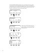
• PowerupeveryOutBackdeviceconnecteddirectlyorindirectly(throughtheHUB)tothe
MATEandthenconnecttheCAT5cabletothejackand,ifused,thecomputerserialcable
totheRS-232port,onthebackMATEorMATE2.
• IfinstallingtheMATE,snaptheMATEontothebackplateandpushanyexcesscableback
intothewall.IfinstallingtheMATE2version,secureitsfourcornerstothewall.
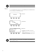
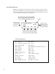
DC ‡ AC ……………….0.0 kW
AC L oad …. ……………………..
Buying ………………………….
Battery …………….…14.4V
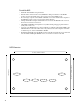
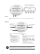
MATE2 Dimensions
15.875 cm (6 1/4”)
11.43 cm (4 ½”)
8.89 cm (3 ½” ) between screw holes
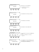
To Install the MATE:
12.7 cm (5” ) between screw holes
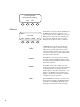
A C IN
I NV