
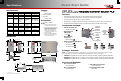
ICSPLUS Quick Start Guide

Additional Applications
Other Applications
In systems where other system elements are required, the ICS Plus can be used with third-party equipment. Some
systems may only need certain ICS Plus components, rather than the entire system. This may depend on the
applicable code requirements.
Other applications not depicted here include:
PV equipment with voltages in excess of 300 Vdc
No requirement for PVRSS
Non-battery-based systems
Positive-grounded systems
See the ICS Plus Owner’s Manual for more details on these specialized systems.
The instructions in this document assume a negative-grounded system, the use of a battery bank with 18 to 68 Vdc
available (a 24/48-volt nominal bank) and the use of BKR-CTRL-DC, the Circuit Breaker Control Box. An isolated
Class 2 DC power supply with the following specifications must be installed if BKR-CTRL-DC is not in use:
o 24 Vdc ± 3% maximum over input voltage, ambient temperature, output load, and initial accuracy
o Up to 1.5 Adc
This requirement may apply under the following conditions:
Non-battery-based systems
Battery-based systems with a different battery voltage than that stated above.
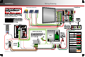
Multiple Combiners
Up to six combiners can be used with a single Rapid Shutdown Initiator. The RSI can be used as an emergency
shutoff for all of the six systems. Also, if any of the arrays suffer an arc fault, the RSI arc fault indicator will show
that the fault has occurred. Six combiners can be powered by a single BKR-CTRL-DC.
Connect the control wires of additional combiners in series with the first combiner (designated below).
The J1 terminals for are connected to the RSI as shown on the previous page. The J2 terminals are
connected to the J1 terminals on . The J2 terminals on are connected to the J1 terminals on
if present, and so on.
NOTE: J1 and J2 are interchangeable in the combiner and can be reversed if necessary. (See the connections between
and below.) This statement is only true for combiner boxes.
Multiple Combiners
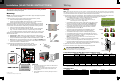
Surge Protector
An optional surge protection device can be installed in the combiner. A knockout has been provided to
accommodate this type of device. This image shows the underside of the combiner and the location of
the knockout.
1
2 3 4
56
Contact Information
OutBack Power Technologies
17825 – 59
th
Avenue NE
Suite B
Arlington, WA 98223
Telephone: +1.360.435-6030
+1.360.618-4363 (Tech Support)
+1.360.435.6019 (Fax)
Email: Support@outbackpower.com
Website: www.outbackpower.com
Date and Revision
June 2016, Revision A
To RSI
J2 J1
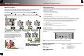
In installations where the RTB is in use, additional
combiners require additional RTB devices. One RTB
pole is required for rapid shutdown of each PV circuit.
For six arrays, the recommended method is to use one
PNL-75Q-DC-RT for shutdown of four arrays and one
PNL-75D-DC-RT for the other two. The BKR-CTRL-DC
can drive up to three RTB devices.
To BKR-CTRL-DC
To charge controllers (1 through 6)
PV Conduit PV Cable
Glands
Communications
Conduits
Surge
Protector
NOTE: Any installed devices must be liquid-tight to sustain the combiner’s environmental rating.
J2 J1 J2 J1 J2 J1
J2 J1 J2 J1
1
2
3
4
5
1
2
900-0183-01-00 REV A
©2016 OutBack Power Technologies. All Rights Reserved.