
Product Manual
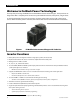

Table of Contents
6 900-0198-01-00 Rev A
List of Figures
Figure 1 FX Mobile Series Inverter/Charger with Turbo Fan ............................................................................. 8
Figure 2 MATE, MATE2, MATE3, and AXS Port ........................................................................................................ 9
Figure 3 LED Indicators ................................................................................................................................................ 11
Figure 4 Inverter Status LED Indicators .................................................................................................................. 12
Figure 5 Charging Stages (Auto Setting) ............................................................................................................... 19
Figure 6 Charging Stages (On Setting) ................................................................................................................... 20
Figure 7 OutBack HUB10.3, MATE, MATE2 , and MATE3 .................................................................................. 25
Figure 8 Example of Classic Series Stacking Arrangement ............................................................................. 26
Figure 9 Example of OutBack Series Stacking Arrangement .......................................................................... 27
Figure 10 Example of Parallel Stacking Arrangement (Three Inverters) ....................................................... 27
Figure 11 Example of Series/Parallel Stacking Arrangement (Four Inverters) ............................................ 28
Figure 12 Example of Three-Phase Stacking Arrangement (Three Inverters) ............................................. 28
Figure 13 Power Save Levels and Loads ................................................................................................................... 29
Figure 14 Power Save Priority (Parallel) .................................................................................................................... 30
Figure 15 Power Save Priority (Split-Phase) ............................................................................................................ 31
Figure 16 Home Screen .................................................................................................................................................. 35
Figure 17 Inverter Screens ............................................................................................................................................. 35
Figure 18 Battery Screen ................................................................................................................................................ 36
Figure 19 AC Test Points................................................................................................................................................. 37