
Product Manual


Specifications
54 900-0198-01-00 Rev A
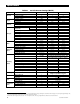
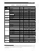
Table 23 24-Volt Inverter Settings (MATE3)
Field Item Default Minimum Maximum
INVERTER
Hot Key
Inverter Mode
Off On, Off, or Search
CHARGER
Hot Key
Charger Control
On On or Off
AC Input
Hot Key
AC Input Mode
Use Drop or Use
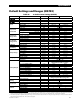
Search
Sensitivit
y
(see page 14 for increments)
6 0 50
Pulse Length
8 AC Cycles 4 AC Cycles 20 AC Cycles
Pulse Spacing
60 AC Cycles 4 AC Cycles 120 AC Cycles
AC Input and
Current Limit
Input Type Gri
d
Grid or Gen
Grid Input AC Limit
28 Aac 5 Aac 30 Aac
Gen Input AC Limit
28 Aac 2 Aac 30 Aac
Charger AC Limit
FX2524MT 12 Aac 0 Aac 14 Aac
VFX3524M 18 Aac 0 Aac 20 Aac
Grid AC Input
Voltage Limits
Voltage Limit Lower
108 Vac 40 Vac 115 Vac
(Voltage Limit) Upper
140 Vac 130 Vac 150 Vac
Transfer Delay
0.1 second 0.12 seconds 4.0 seconds
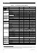
Gen AC Input
Voltage Limits
Voltage Limit Lower
108 Vac 40 Vac 115 Vac
(Voltage Limit) Upper
140 Vac 130 Vac 150 Vac
Transfer Delay
1.0 second 0.12 seconds 4.0 seconds
Connect Dela
y
0.5 minutes 0.2 minutes 15.0 minutes
AC Output
Output Voltage
120 Vac 110 Vac 125 Vac
Low Battery
Cut-Out Voltage
21 Vdc 18 Vdc 24 Vdc
Cut-In Voltage
25 Vdc 22 Vdc 26 Vdc
Battery Charger
Absorb Voltage
28.8 Vdc 26 Vdc 32 Vdc
(Absorb) Time
1.0 hours 0.0 hours 24.0 hours
Float Voltage
27.2 Vdc 24 Vdc 30 Vdc
(Float) Time
1.0 hours 0.0 hours 24.0 hours
Re-Float Voltage
25 Vdc 22 Vdc 26 Vdc
Battery Equalize
Equalize Voltage
28.8 Vdc 28 Vdc 34 Vdc
(Equalize) Time
1.0 hours 0.0 hours 24.0 hours
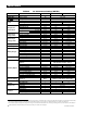
Auxiliary Output
Aux Control Auto Off, Auto or On
Aux Mode
Cool Fan Cool Fan, DivertDC, DivertAC, AC Drop, Vent Fan,
Fault, GenAlert, LoadShed, or Remote
(Load Shed) Enable Voltage
22 Vdc 20 Vdc 28 Vdc
(Gen Alert) ON Voltage
22 Vdc 20 Vdc 28 Vdc
(Gen Alert ON) Dela
y
4 minutes 0 minutes 240 minutes
(Gen Alert) OFF Voltage
28 Vdc 24 Vdc 36 Vdc
(Gen Alert OFF) Dela
y
9 minutes 0 minutes 240 minutes
(Vent Fan) Enable Voltage
26 Vdc 20 Vdc 32 Vdc
(Vent Fan) Off Perio
d
5 minutes 0 minutes 30 minutes
(Divert DC or AC) Enable Voltage
29.2 Vdc 24 Vdc 32 Vdc
(Divert DC or AC) Off Dela
y
30 seconds 0 seconds 240 seconds
Inverter Stacking
Stack Mode Master
1-
2
phase Master, Classic Slave, OB Slave L1,
OB Slave L2, 3phase Master, 3phase Slave
Power Save
Ranking
Master Adjust Onl
y
0 0 7
Slave Adjust Only
1 1 15
Grid-Tie Sell
Gri
d
Tie Enable
— Inoperative
Sell Voltage
— Inoperative
Grid Tie Windo
w
— Inoperative
Calibrate
Input Voltage
21
-1 -3 1
Output Voltage
21
-1 -3 1
Battery Voltage
22
0.0 -0.4 0.4
21
These values represent an adjustable setting with a total range of 4 Vac. The default value of -1 means the calibration will subtract 1 volt from the measured value.
The range of settings allow up to 1 volt to be added to the measured value, or up to 3 volts to be subtracted from it. The result is also displayed.
22
These values represent an adjustable setting with a range of ± 0.4 Vdc from the measured value. The range of settings allows up to 0.4 volts to be either added or
subtracted from the measured value (in increments of 0.2 Vdc). The result is also displayed.