
Product Manual


Troubleshooting
900-0198-01-00 Rev A 41
Warning Messages
A warning message is caused by a non-critical fault. When this occurs, the ERROR indicator will flash,
although the inverter will not shut down. (See page 11 for the FX inverter’s LED indicators.) The system
display has a list of warning messages. One or more messages will display
yes
in the MATE or MATE2. It
will display
Y
in the MATE3 along with an event message. If a message says
no
or
N
, it is not the cause of
the warning. See the system display literature for more instructions.
Some warnings can become errors if left unattended. Frequency and voltage warnings are meant to warn
of a problematic AC source. Often the inverter will disconnect from the source. This will occur if the
condition lasts longer than the inverter’s transfer delay settings. If the inverter disconnects, the warning
will display as long as the source is present, accompanied by a disconnect message. (See page 42.)
Warning screens can only display warnings; they cannot clear them. The way to correct the fault may be
obvious from the message.
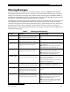
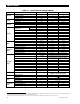
Table 7 Warning Troubleshooting
Message Definition Possible Remedy
A
C Freq Too High
The AC source is above the upper acceptable
frequency limit and prevents connection.
Check the AC source. If it is a generator, reduce its
speed.
AC
Freq Too Lo
w
The AC source is below the lower acceptable
frequency limit and prevents connection.
Check the AC source. If it is a generator, increase its
speed.
Voltage Too High
The AC source is above the upper acceptable
voltage limit and prevents connection.
Check the AC source. The inverter’s acceptance
range is adjustable.
NOTE:
Adjusting the range may accommodate a
problematic AC source, but it will not fix it.
Voltage Too Lo
w
The AC source is below the lower acceptable
voltage limit and prevents connection.
Check the AC source. Check the AC wiring. The
inverter’s acceptance range is adjustable.
NOTE:
Adjusting the range may accommodate a
problematic AC source, but it will not fix it.
Input
A
mps > Ma
x
AC loads are drawing more current from the
AC source than allowed by the input setting.
Check the loads. Oversized loads can open circuit
breakers. If they exceed the inverter’s transfer relay
size, the relay can be damaged.
This issue is usually the result of a poorly-sized load,
as opposed to a wiring problem.
Temp Sensor Ba
d
An internal inverter temperature sensor may
be malfunctioning. One of the three internal
sensor meters may give an unusual reading.
In the MATE3, the three readings are labeled
Transformer, Output FETs,
and
Capacitors
. These
values are given in degrees Celsius. See next page.
Internal Comm Error
Probable failure on inverter’s control board.
Despite the name, this is not an inverter-
defined error and is not accompanied by
a shutdown.
Unit may require repair. Contact OutBack Technical
Support
7
.
Fan Failure
T
he inverter’s internal cooling fan is not
operating properly. Lack of cooling may
result in derated inverter output wattage.
Turn the battery disconnect off, and then on, to
determine if the fan self-tests. After this test, contact
OutBack Technical Support.
7
(The next step will
depend on the results of the test.)
NOTE:
The system can continue to operate if the
inverter can be run at reasonable levels. External
cooling may also be applied.
7
See inside front cover of this manual.