
Product Manual


Metering
36 900-0198-01-00 Rev A
Charge
displays the kilowatts and AC amperage consumed for the inverter to charge the battery bank. This line
also shows the present charging stage.
Load
displays kilowatts and AC amperage consumed by devices on the inverter’s output. It can be the same
as
Invert
.
Buy
displays the kilowatts and AC amperage brought into the inverter’s input for both charging and loads. This
is usually a total of
Charge
and
Load
.
Battery
displays the uncompensated battery voltage.
AC Out
displays the AC voltage measured at the inverter’s output. If an AC source is present, this reading is
usually the same as
AC In
.
AC In
displays the AC voltage measured at the inverter’s input from an AC source. This number may be erratic or
inaccurate upon first connection until the inverter synchronizes with the input source.
AUX
displays the current status of the inverter’s Auxiliary (AUX) 12-volt output. (See page 31.)
A diode symbol may appear to the left of the screen name to indicate “diode charging” mode. This is a mode that
allows fine control of charging, selling, and load support. It does not visibly affect operation.
The
<Graph>
soft key brings up a series of screens which plot various types of data over time on the
MATE3 screen.
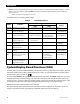
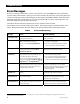
Battery Screen
The
<Next>
soft key brings up a screen showing charger status, charger settings, and battery voltage and
temperature information.
Figure 18 Battery Screen
Screen items:
Actual
displays the uncompensated battery voltage.
Absorb
displays the charger’s Absorption voltage setting. (See page 20.)
Float
displays the charger’s Float voltage setting. (See page 21.)
Equalize
displays the charger’s Equalization voltage setting. (See page 23.)
Temp Comp
displays the corrected battery voltage using temperature readings from the Remote Temperature
Sensor (RTS). If no RTS is present,
Temp Comp
and
Actual
will read the same. (See page 23.)
Batt Temp
displays the battery temperature in degrees Celsius as measured by the RTS. This reading is only valid
for port 1 on the HUB product. If other ports are selected, or if no RTS is present, the characters ### will be displayed.
Re-Float
displays the Re-Float setting which was programmed into the inverter’s charger. This is the voltage
used for the inverter to return from Silent mode to the float stage. (See page 21.)
The
<Warn>
and
<Error>
keys bring up screens with various fault information. See the next section.
NOTE: The charger settings cannot be adjusted on this screen.
An arrow will appear to the right of
Absorb, Float
, or
Equalize
to indicate that the charger is in that stage. The arrow will not appear
if the charger is in the Bulk stage, or if it is inactive.