
Product Manual


Operation
30
900-0198-01-00 Rev A
NOTE:
The stacking designations also control which ports are used on the HUB
communications manager. The master inverter must be plugged into port 1. Other
ports and jumper positions vary with model and stacking configuration.
IMPORTANT:
Set the master rank at 0 and arrange the slave ranks in order (1, 2, 3, 4, etc.). Another
order may defeat the purpose of Power Save mode. Leaving the master at 0 makes
power available from the master; the other inverters should not be active. If a slave is
ranked lower (prioritized higher) than the master, that slave will not go silent.
NOTE:
Disregard this rule if the installation requires some slaves continuously active.
IMPORTANT:
Do not give slave inverters the same rank numbers. If, for example, multiple slaves were
all ranked at 1, they would all come on at the same time. Once they came on, the
divided load would cause the master to detect a minimal load on its output, so it would
shut off all the slaves, at which point the master would read a high load again. This
could quickly escalate into a rapid on/off cycling of inverters and could cause long-term
system problems.
NOTE
: Power Save is used by the battery chargers of stacked systems with slave inverters. Not all
chargers are activated immediately. Initially the master is the only active charger. The batteries will
absorb current up to the maximum for all chargers. When the batteries (and the master) draw more than
12 Aac, the master will turn on the first slave charger. The batteries will absorb that additional current and
more. The master will then turn on more slaves until all active chargers are operating.
If the master
Charger AC Limit
is turned to 11 or less, it will not turn on any slaves and will remain the only
charger. For more information on charging with stacked inverters, see page 19.
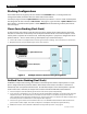
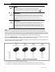
Figure 14 shows a system of four FX2012MT inverters (the master and three slaves). These inverters are in
a parallel system with a common load bus.
Figure 14 Power Save Priority (Parallel)
The captions at the top indicate the ranking of each unit.
The captions also show the port assignments on the HUB4 Communications Manager (1 through 4).
The notations at the bottom show how the units are activated in sequence as loads of 12 Aac are applied.
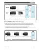
Master
Slave 1 Slave 3 Slave 2
Port 1
Master Power Save = 0
Port 2
Slave Power Save = 1
Port 4
Slave Power Save = 3
Port 3
Slave Power Save = 2
<12 Aac On Off Off Off
12 Aac On On Off Off
24 Aac On On On Off
36 Aac On On On On
16 Aac On On On Of
f