
Product Manual


Operation
26 900-0198-01-00 Rev A
Stacking Configurations
Each inverter must be assigned a particular mode in the
Stack Mode
menu. In the figures for each
configuration below, the mode names are shown next to each inverter.
For example, Figure 8 shows
1-2phase Master
for the first (L1) inverter in a “classic” series-stacked system.
The designation for the L2 inverter is
Classic Slave
. On page 27, Figure 10 shows
1-2phase Master
for the
first inverter in a parallel-stacked system. It shows
OB Slave L1
for the remaining inverters, which share
the same output.
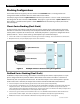
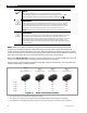
Classic Series Stacking (Dual-Stack)
In series stacking, two inverters create two separate 120 Vac output phases. One inverter is the master.
The other is a slave that is intentionally 180° out of phase with the master. Each of these outputs can be
used to power a separate set of 120 Vac loads. Collectively they form a “split-phase” configuration which
produces 240 Vac. “Classic” series stacking is the simplest way to achieve this output.
The 120 Vac loads on each output cannot exceed a given inverter’s wattage. The second inverter cannot assist.
Only two inverters, one per output, may be classic series stacked.
Figure 8 Example of Classic Series Stacking Arrangement
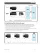
OutBack Series Stacking (Dual-Stack)
In OutBack’s unique series stacking, two inverters create two separate 120 Vac output phases in a “split-
phase” configuration which produces 240 Vac. One inverter is the master. The other is a slave that is
intentionally 180° out of phase with the master. Each of these outputs can be used to power a separate
set of 120 Vac loads. However, the output loads are balanced with the FW-X240 autotransformer.
The slave output is controlled directly by the master and cannot operate independently.
In the event of a load imbalance in a 120/240 Vac system, the FW-X240 transformer can transfer power from one
output to the other. The transfer balances the loads on each inverter. It also allows heavy 120 Vac loads on
either output to use the full power of both inverters. (The loads in Figure 9 are marked “2+ kVA” per output. This
means the power of a 2 kVA inverter is assisted by the other output.)
The slave can go into Power Save mode when not in use. The FW-X240 autotransformer allows the master to
power loads on either output. This reduces idle power consumption and improves system efficiency.
Additional inverters can be added for combination series/parallel operation. See page 28.
2.0 kVA
120 Vac
4.0 kVA
240 Vac
2.0 kVA
120 Vac
2.0 kVA 120 Vac
2.0 kVA 120 Vac
LOAD
OR
1-2phase Master (L1)
Classic Slave (L2)