
Product Manual


Operation
900-0198-01-00 Rev A
25
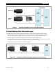
Multiple-Inverter Installations (Stacking)
Multiple inverters in a single system can support larger loads than a single inverter. Installing inverters in
this configuration is called “stacking”. Stacking refers to how inverters are wired within the system and
programmed to coordinate activity. Stacking allows inverters to work together as one system.
Each inverter is programmed to power an individual phase of the system and to operate at certain times.
This order is assigned using a system display such as the OutBack MATE, MATE2, or MATE3. FX stacking
configurations include “classic series”, “OutBack series”, “parallel”, “series/parallel”, and “three-phase”.
Each inverter needs to be assigned a status — “master” or “slave”. The master provides the primary (L1)
output. Slave inverters provide assistance when a master on any output cannot power the loads alone. See
the FX Mobile Series Inverter/Charger Installation Manual for more information.
Stacking requires CAT5 non-crossover cable used with an OutBack HUB Communications Manager (either the
HUB4 or the HUB10.3).
The inverter on each port must be programmed with a status and stacking value. Different HUB products use
different port assignments. There are usually other specialized instructions during installation.
An AC source for a split-phase or three-phase system should provide input to all inverters on all phases. A
slave inverter will give a
Phase Loss
warning if it is not supplied. (See pages 17 and 41.)
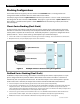
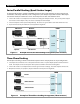
Figure 7 OutBack HUB10.3, MATE, MATE2 , and MATE3
IMPORTANT:
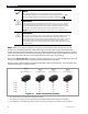
The master inverter must always be connected to Port 1 on the HUB product. Connecting it
elsewhere, or connecting a slave to Port 1, will result in backfeed or output voltage errors
which will shut the system down immediately.
All stacked inverters must be the same model and firmware revision.
Installing multiple inverters without stacking them (or stacking them incorrectly) will result
in similar errors and shutdown.
Although stacking allows greater capacity, the loads, wiring, and overcurrent devices must
still be sized appropriately. Additional terminations or bus bars may be required.
Overloading may cause circuit breakers to open or inverters to shut down.
Additional Ports
Port 1
MATE
HUB10.3
Communications
Manager
MATE2 System Display
MATE3 System Display
MATE System Display