
Product Manual


Operation
20 900-0198-01-00 Rev A
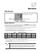
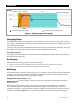
Figure 6 Charging Stages (On Setting)
Charging Steps
The following items describe the operation and intended use for each individual charging step as shown
in the graphs. Note that some charging cycles may not follow this exact sequence, including cycles which
were previously interrupted.
See page 22 for a description of multiple cycles when the charger is restarted after completion. This page
also describes multiple cycles when the charger is restarted after being interrupted.
For multiple inverters:
The charging of stacked inverters is synchronized and is governed by the master. The charger settings of
all other inverters are ignored.
No Charging
If the inverter is not charging, several conditions may apply:
The unit is not connected to a qualified AC source. If a generator is present, it may not be running.
The unit is connected to an AC source but the charger has been turned off.
Bulk Stage
This is the first stage in the three-stage charge cycle. It is a constant-current stage which drives the battery
voltage up. This stage typically leaves the batteries at 75% to 90% of their capacity, depending on the
battery type, the exact charger setting, and other conditions.
Voltage Used:
Absorb Voltage
setting.
Default Set Point
(nominal voltage): 14.4 Vdc (12-volt). This is multiplied accordingly for inverters of
other voltages.
The initial DC current may be as high as the charger’s maximum current, depending on conditions.
The current will begin at a high level, but will tend to drop slightly as the voltage rises. This is not a
reduction in charging. It can be viewed as a wattage “tradeoff”. The actual kilowatts used by the charger
are shown in the MATE3
Inverter
menu. The reading is usually consistent at this stage. (See page 35.)
Voltage
Inverter now charging to a new set point Inverter has reached the charging set point
No Charge (Source Removed)
Time
Absorption
Set Point
Float
Set Point
Bulk Absorption Float
No Charge