
Product Manual


Operation
900-0198-01-00 Rev A 19
Charge Current for Multiple Inverters
If FX inverters are stacked, the master inverter
Charger AC Limit
setting is used by all other inverters.
Divide the total AC current by the number of chargers used and program the master with the result. The
master will operate all chargers with this setting to achieve the maximum total charge current. The
system display has a global
Charger Control
command of
On
which enables all available chargers.
Limiting Charge Current (Multiple Inverters)
It is not advisable to set
Charger AC Limit
less than 12 Aac in a stacked system. The Power Save function
requires the master to activates the slave chargers in sequence only when the charge current exceeds
11 Aac. If the setting is less than 12, Power Save will not activate any other chargers.
For more information on this function, see the Power Save section beginning on page 28.
Charge Cycle
FX and VFX mobile inverters use a “three-stage” battery charging process with Bulk, Absorption, and Float
stages. These stages follow a series of steps which are shown on graphs and described beginning below.
The inverter’s factory default settings are intended for three-stage charging of lead-acid batteries.
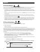
Charging Graphs
When the charger is set to <
Auto
> using the system display, the charger automatically progresses
through a three-stage cycle. Upon completion, the charger switches between Float stage and Silent mode
as described on page 21. This is often selected to maintain batteries from shore power.
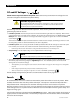
Figure 5 shows the progression of steps of the <
Auto
> charging cycle.
Figure 5 Charging Stages (Auto Setting)
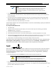
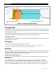
When the charger is set to <
On
> using the system display, the charger automatically progresses through a
three-stage cycle. However, this setting eliminates the Silent and Refloat steps. The charger remains in
Float continuously. The Float stage lasts until the AC source is removed. This is often selected when
charging from an automatic generator which shuts down at the Float stage.
Figure 6 on the next page shows the progression of steps of the <
On
> charging cycle.
Voltage
Time
Inverter now charging to a new set point
Inverter has reached the charging set point
Inverter completed charging; the previous set point is no longer in use
Bulk
ReFloat
Absorption
FloatSilent
Absorption
Set Point
Float
Set Point
Re-Float
Set Point
No Charge
Silent
ReFloat
Float Silent
Refloat