
Product Manual
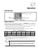


Operation
18
900-0198-01-00 Rev A
Battery Charging
IMPORTANT:
Battery charger settings need to be correct for a given battery type. Always follow battery
manufacturer recommendations. Making incorrect settings, or leaving them at factory default
settings, may cause the batteries to be undercharged or overcharged.
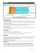
Charge Current
Batteries or battery banks usually have a recommended limit on the maximum current used for charging.
Often this is calculated as a percentage or fraction of the battery capacity, represented by “C”. For
example, C/5 would be a DC amperage figure that is 1/5 of the total amp-hours of the bank.
Any chargers must be set so that the peak charge current does not exceed the recommended battery
maximum. If multiple chargers are present (including other types of chargers besides the inverter), this
calculation must accommodate the total combined current. The FX charger may need to be set at less
than maximum. The system display can be used to change charger settings.
IMPORTANT:
Although the recommended current is generally represented in DC amperes (Adc), the
Charger
AC Limit
setting is measured in AC amperes (Aac), which use a different scale. To convert the
DC current into a usable AC figure, divide the DC figure by the following number (based on
inverter voltage) and round up. The result can be used as a charger setting for the FX inverter.
12-volt inverters: Divide by 10
24-volt inverters: Divide by 5
32-volt inverters: Divide by 3.33
36-volt inverters: Divide by 3.75
48-volt inverters: Divide by 2.5
Examples
:
1)
Bank consists of 8 x L16 FLA batteries in series for a 48-volt system. Recommended
maximum charge current is 75 Adc. (75 ÷ 2.5 = 30 Aac)
2)
Bank consists of 6 x OutBack EnergyCell 200RE VRLA batteries in series/parallel for a 24-volt
system. Recommended maximum charge current is 45 Adc. (45 ÷ 5 = 9 Aac)
The maximum DC charge rate for FX models is specified in Table 9 on page 43. The actual
Charger
AC Limit
setting is available in the
AC Input and Current Limit
menu of the MATE3 system display.
(See the menu tables which begin on page 53.) These numbers are also summarized in Table 2.
NOTE
: This table does not match the calculations above due to other factors in charging.
Table 2 Charge Currents for FX and VFX Mobile Models
Model Maximum DC Output (sent to battery) Maximum AC Input (used from source)
FX2012MT 80 Adc 12 Aac
FX2024M 40 Adc 12 Aac
FX2524MT 55 Adc 14 Aac
FX2532MT 35 Adc 14 Aac
FX2536MT 35 Adc 14 Aac
FX3048MT 35 Adc 14 Aac
VFX2812M 125 Adc 16 Aac
VFX3524M 82 Adc 20 Aac
VFX3232M 45 Adc 20 Aac
VFX3236M 45 Adc 20 Aac
VFX3648M 45 Adc 20 Aac