
Installation Manual


Installation
42 900-0197-01-00 Rev A
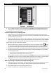
Figure 32 AC Terminals
4. Using a DVM or voltmeter, measure between the AC HOT OUT and AC NEUTRAL OUT terminals.
(See Figure 32.) The inverter is working correctly if the AC output reads within 10% of 120 Vac.
Proceed past the items below to Step 5.
To start a multiple-inverter (stacked) system:
1. Close the main DC circuit breakers (or connect the fuses) from the battery bank to the master
inverter. The inverter will activate. Do not turn on any AC circuit breakers at this time. Confirm that
the system display is operational.
2. Observe the LED indicators in the AC wiring compartment. One of the three BATTERY indicators
should be illuminated (green, yellow, or red). Any of them are acceptable at this stage. INVERTER
(green) should come on at this time. The fan will run briefly and the relay will click as a self-test.
Repeat steps 1 and 2 for every inverter present.
3. With the system display, perform programming for stacking and all other functions. These
functions may include input current limits, battery charging, and generator starting. All parallel-
stacked slave inverters will observe the master programming settings and do not need to be
programmed individually. The MATE3 Configuration Wizard may be used to assist programming.
4. Using the system display, temporarily bring each slave out of Silent mode by raising the Power
Save Level of the master.
As each slave is activated, it will click and create an audible hum.
Confirm that the system display shows no fault messages.
Using a DVM or voltmeter, measure between the AC HOT OUT terminal on the master inverter and
AC HOT OUT on each slave. Series inverters should read within 10% of 120 Vac. Parallel inverters
should read close to zero. Three-phase inverters should read within 10% of 208 Vac.
When this test is finished, return the master to its previous Power Save Level.
After output testing is completed, perform the following steps:
5. Close the AC output circuit breakers. If AC bypass switches are present, place them in the normal
(non-bypass) position. Do not connect an AC input source or close any AC input circuits.
6. Use a DVM to verify correct voltage at the AC load panel.
7. Connect a small AC load and test for proper functionality.