
Installation Manual


Installation
38 900-0197-01-00 Rev A
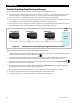
Three-Phase Stacking
In three-phase stacking, inverters create three separate 120 Vac output phases in a wye configuration.
The output of each inverter is 120° out of phase from the others. Any two outputs produce 208 Vac between
them. The outputs can be used to power three-phase loads when all inverters work together.
The 120 Vac loads on each output cannot exceed a given inverter’s wattage. The other outputs cannot assist.
Only three inverters, one per phase, may be installed in a three-phase arrangement. All inverters must be the
same model.
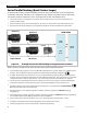
Figure 30 Example of Three-Phase Stacking Arrangement (Three Inverters)
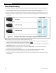
When installing a three-phase system, observe the following rules.
Three-phase stacking requires both a system display and a communications manager. Port assignments and
jumper positions vary with model and stacking configuration.
The master must be connected to communications manager port 1. It is the Phase A output. It is programmed as
3phase Master
. Other inverters must not be selected as master.
The Phase B and Phase C inverters must be programmed as
3phase Slave
. See the HUB Communications
Manager literature for port assignments.
All overcurrent devices must be sized for 30 Aac or less. All wiring must be sized for 30 Aac or more.
All output circuit breakers must be sized appropriately for loads and inverter power.
The AC input (generator or utility grid) must be a three-phase wye configuration source of the proper voltage
and frequency.
2.0 kVA 120 Vac
2.0 kVA 120 Vac
2.0 kVA 120 Vac
2.0 kVA
120 Vac
6.0 kVA
208 Vac
2.0 kVA
120 Vac
2.0 kVA
120 Vac
LOAD PANEL
OR
3phase Slave (C)
3phase Slave (B)
Master (A)