
Installation Manual


Installation
32 900-0197-01-00 Rev A
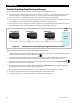
OutBack Series Stacking (Dual-Stack)
In OutBack’s unique series stacking, two inverters create a “split-phase” configuration. This configuration
creates two separate 120 Vac output legs. One output is the master. The other is a slave that is
intentionally 180° out of phase with the master. The collective voltage is 240 Vac, as in Classic stacking.
However, the output loads are balanced with the FW-X240 autotransformer.
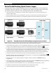
The slave output is controlled directly by the master and cannot operate independently.
In the event of a load imbalance in a 120/240 Vac system, the FW-X240 transformer can transfer power from one
output to the other. The transfer balances the loads on each inverter. It also allows heavy 120 Vac loads on
either leg to use the full power of both inverters. (The loads below are marked “2+ kVA” per output. This means
the power of a 2 kVA inverter is assisted by the other output.)
The slave can go into Power Save mode when not in use. The FW-X240 autotransformer allows the master to
power loads on either output. This reduces idle power consumption and improves system efficiency.
Additional inverters can be added for combination series/parallel operation. See page 36. All inverters must be
the same model.
Figure 24 Example of OutBack Series Stacking Arrangement
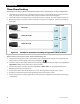
When installing an OutBack series system, the following rules must be observed.
Series stacking requires an FW-X240 autotransformer, a system display and a communications manager. Port
assignments and jumper positions vary with model and stacking configuration.
The inverter that is mounted physically lowest is designated as the master. It is the L1 output. Mounting the
master below the other inverters allows the master to avoid heat buildup and remain relatively cool.
The master must be connected to communications manager port 1. It is programmed as
1-2phase Master
.
Other inverters must not be selected as master.
The L2 inverter must be programmed as
OB Slave L2
during programming. See the HUB Communications
Manager literature for port assignments.
All overcurrent devices must be sized for 30 Aac or less. All wiring must be sized for 30 Aac or more.
All output circuit breakers must be sized appropriately for loads and inverter wattage.
The AC input (generator or shore power) must be 120/240 Vac (split-phase).
2.0 kVA 120 Vac
2+ kVA
120 Vac
2.0 kVA 120 Vac
2+ kVA
120 Vac
4.0 kVA
240 Vac
FW-X240
LOAD PANEL
OR
OB Slave L2
1-2phase
Master