
Installation Manual


Installation
30 900-0197-01-00 Rev A
Stacking Configurations
Classic Series Stacking (Dual-Stack)
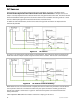
In series stacking, two inverters create two separate 120 Vac output phases. One inverter is the master.
The other is a slave that is intentionally 180° out of phase with the master. Each of these outputs can be
used to power a separate set of 120 Vac loads. Collectively they form a “split-phase” configuration which
produces 240 Vac. “Classic” series stacking is the simplest way to achieve this output.
The two outputs operate independently of each other. The 120 Vac loads on each output cannot exceed a given
inverter’s size. The second inverter cannot assist.
Only two inverters, one per output, may be classic series stacked. They must be the same model.
Figure 22 Example of Classic Series Stacking Arrangement
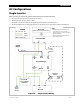
When installing a series inverter system, observe the following rules.
Series stacking requires both a system display and a communications manager. Port assignments and jumper
positions vary with model and stacking configuration.
The master inverter is the L1 output. It must be connected to communications manager port 1. It is
programmed as
1-2phase Master
. Other inverters must not be selected as master.
The L2 inverter must be programmed as
Classic Slave
during programming. See the HUB Communications
Manager literature for port assignments.
All overcurrent devices must be sized for 30 Aac or less. All wiring must be sized for 30 Aac or more.
All output circuit breakers must be sized appropriately for loads and inverter power.
The AC input (generator or shore power) must be 120/240 Vac (split-phase).
2.0 kVA
120 Vac
4.0 kVA
240 Vac
2.0 kVA
120 Vac
2.0 kVA 120 Vac
2.0 kVA 120 Vac
LOAD PANEL
OR
1-2phase
Master
Classic
Slave