
Installation Manual


Installation
900-0197-01-00 Rev A
29
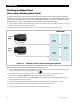
There are two types of slave modes. The names used here are derived from their references onscreen.
A “classic” slave is used for stacking when the slave operates semi-independently of the master. Although the
master sets the phase relationship, the slave creates an output independent of the master. It is not possible to
balance the outputs with the FW-X240 transformer using this method. This type of system is used for the most
basic form of series stacking (two inverters only) and for three-phase stacking.
~ Classic-stacked inverters can go into Search mode independently of the master if necessary.
An “OutBack” slave is used for parallel or series/parallel systems. In parallel stacking, all slaves are in phase with
the master. In series/parallel systems, some slaves are in phase with the master and some are 180° out of phase.
The FW-X240 autoformer can balance the loads of OutBack-stacked inverters.
~ All slave outputs are pulse-width-matched to be precisely synchronized with the master inverter. This avoids potential
backfeed situations.
~ OutBack slaves can be placed in Power Save mode when not in use. They are activated by the master inverter as
needed. For this reason, the master is normally the only inverter to enter Search mode. See the Operator’s Manual for
descriptions of Power Save and Search mode.
In many cases the port assignments for secondary inverters (ports 2 to 4 or 2 to 10) is important. In
general it is always important to keep track of units and ports for programming purposes. See the
communications manager and system display literature for more information.
Programming involves using the system display to assign a status and stacking value to the inverter on
each port. Each inverter is assigned to power a specified phase of the system. These assignments can be
changed at any time as long as the master is plugged into port 1.
IMPORTANT:
The master inverter must always be connected to port 1 on the
communications manager. Connecting it elsewhere, or connecting a slave
to port 1, will result in backfeed or output voltage errors which will shut the
system down immediately.
Installing multiple inverters without stacking them (or stacking them
incorrectly) will result in similar errors and shutdown.
Although stacking allows greater capacity, the loads, wiring, and
overcurrent devices must still be sized appropriately. Overloading may
cause circuit breakers to open or the inverters to shut down.
Table 5 shows all applicable modes for each inverter model.
Table 5 Stacking Modes for Mobile FX Inverters
Mode Name
(MATE3 or MATE)
When Used Function
1-2phase Master
or
1-2ph Master
Classic stack ,
OutBack stack
Master inverter for all series and
parallel stacking
Classic Slave
Classic stack (series)
5
Slave inverter for Classic series stack
OB Slave L1
OutBack stack (parallel or
series/parallel)
Slave inverter (in phase with master)
for parallel stack
OB Slave L2
OutBack stack (series or
series/parallel)
Slave inverter (out of phase with master)
for OutBack series stack
3phase Master
or
3ph Master
Three-phase stack
6
Phase A inverter for three-phase stack
3phase Slave
or
3ph Slave
Three-phase stack
6
Phase B or C inverter (phase is assigned
by port) for three-phase stack
5
Two inverters only
6
Three inverters only