
Installation Manual


Installation
24 900-0197-01-00 Rev A
AUX Wiring
The AUX+ and AUX– terminals are a switched 12 Vdc supply. The AUX can respond to different criteria
and control many functions. These include cooling fans, vent fans, load diversion, fault alarms, and the
Advanced Generator Start (AGS) function.
The terminals can supply up to 0.7 amps at 12 Vdc (8.4 watts). This is sufficient to drive a small fan or a
relay controlling a larger device. The terminals accept wire up to #14 AWG (2.5 mm). The
AUX
circuit
contains electronic overcurrent protection, which resets after being overloaded. No additional fuses are
required for the
AUX
terminals.
The default setting for the AUX output is to control the Turbo Fan included with sealed models.
(See Figure 17.) The AUX output can only control one function at a time. It cannot be used for anything
else if the Turbo Fan is connected.
The control logic for the AUX output is not always located in the same device. Inverter AUX functions are
located within the inverter itself and are described accordingly. Although inverter-based functions require
the system display for programming, they will function even if the display is removed. However, AGS
programming is located within the system display and will not work if the display is removed. Other devices
may also be able to control the terminals. For generator control, see page 25.
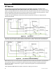
Figure 17 AUX Connections for Vent Fan (Example)
In this example, the AUX
directly drives a 12-volt
vent fan. The + and – wires
on the fan are connected to
the AUX+ and AUX–
terminals.
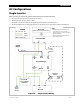
Fan
AUX LED
INDICATOR
The AUX indicator
illuminates when
the AUX output
becomes active.