
Installation Manual

Installation
18
900-0197-01-00 Rev A
DC Wiring
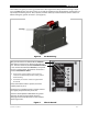
WARNING: Shock Hazard
Use caution when working in the vicinity of the inverter’s battery terminals.
CAUTION: Equipment Damage
Never reverse the polarity of the battery cables. Always ensure correct polarity.
CAUTION: Fire Hazard
The installer is responsible for providing overcurrent protection.
Install a circuit breaker or overcurrent device on each DC positive (+)
conductor to protect the DC system.
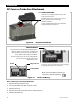
Never install extra washers or hardware between the mounting surface
and the battery cable lug. The decreased surface area can build up heat.
See the hardware diagram on page 19.
IMPORTANT:
The DC terminals must be encased in an enclosure to meet the requirements
of some local or national codes.
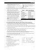
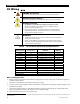
Table 4 contains OutBack’s recommendations for minimum safe cable sizes.
Other codes may supersede OutBack’s recommendations. Consult applicable
codes for final size requirements.
Table 4 DC Conductor Size and Torque Requirements
Inverter
(Wattage/Voltage)
Nominal DC Amps
(Derated 125%)
Conductor Size
4
(Minimum)
Breaker Size
(Minimum)
FX2012MT
200
4/0 AWG (120 mm) or 0.186 in 250 Adc
FX2024M
100
2/0 AWG (70 mm) or 0.109 in 175 Adc
FX2524MT
125
2/0 AWG (70 mm) or 0.109 in 175 Adc
FX2532MT
94
1/0 AWG (70 mm) or 0.109 in 125 Adc
FX2536MT
83
1/0 AWG (70 mm) or 0.109 in 125 Adc
FX3048MT
75
1/0 AWG (70 mm) or 0.109 in 125 Adc
VFX2812M
280
4/0 AWG (120 mm) or 0.186 in 300 Adc
VFX3524M
175
4/0 AWG (120 mm) or 0.186 in 175 Adc
VFX3232M
120
2/0 AWG (70 mm) or 0.109 in 175 Adc
VFX3236M
107
2/0 AWG (70 mm) or 0.109 in 175 Adc
VFX3648M
90
1/0 AWG (70 mm) or 0.109 in 125 Adc
Terminal Location Torque Requirements
Inverter DC Terminals 60 in-lb (6.9 Nm)
Battery Terminals See battery manufacturer’s recommendations
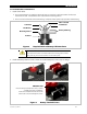
When installing DC cables:
Battery positive and negative cables should be no longer than 10 feet (3 meters) each, to minimize voltage loss
and other possible effects.
Turn off DC circuit breakers or remove fuses before proceeding.
Tie, tape, or twist cables together to reduce self-inductance. Run positive and negative cables through the same
knockouts and conduit.
The inverter’s battery terminal is a threaded stud which accepts a ring terminal lug. Use crimped and sealed
copper ring lugs with 5/16 inch (0.79 cm) holes, or use compression lugs.
Install all overcurrent devices on the positive cable.
4
Cable sizes are for each inverter in a system. In a system with multiple inverters, each inverter requires its own cables and overcurrent devices of
the size indicated.