
Installation Manual

Planning
900-0197-01-00 Rev A 11
E. Conductor efficiency: Wire size and other factors will waste
power due to resistance and voltage drop. Typical
acceptable efficiency is 96 to 99%.
F. Inverter efficiency: FX specifications list “Typical Efficiency”
to help estimate operating loss.
G. System DC voltage: Each inverter model requires a specific DC voltage to operate.
H. Battery voltage: Most individual battery voltages are less than the system DC voltage. The batteries may need to be
placed in series to deliver the correct voltage.
I. Capacity: Battery capacity, which is measured in
amp-hours, is not usually a fixed number. It is
specified based on the rate of discharge. For example,
the OutBack EnergyCell 200RE is rated at 134.5 Ahr
when discharged at the 5-hour rate (to terminal
voltage 1.85 Vpc). This is a high rate of discharge that
would hypothetically drain the battery in 5 hours.
The same battery is rated at 191 Ahr when used at the
100-hour rate. Use the appropriate discharge rate
(correlated to the expected loads) to measure the
capacity of a battery. Use battery specifications for
terminal voltage 1.85 Vpc whenever possible.
NOTE: Capacity ratings are for batteries at 25°C.
Capacity is reduced at cooler temperatures.
J. Maximum depth of discharge (DoD): Most batteries cannot be discharged below a certain level without damage. The
bank requires enough total capacity to keep this from happening.
To Calculate Minimum Battery Bank Size (refer to Table 2 for letter designations):
1.
The load size, item A, is measured in watts. Compensate this figure for efficiency loss. Multiply the
conductor efficiency by the inverter efficiency (E x F). (These items are represented as percentages, but
may be displayed as decimals for calculation.) Divide item A by the result.
2. Convert the compensated load into amperes (Adc). Divide the step 1 result by the system voltage (item G).
3. Determine the daily load consumption in ampere-hours (amp-hours, or Ahr). Multiply the step 2 result by
the daily usage hours (item B).
4. Adjust the total for required days of autonomy (the days the system must operate without recharging)
and the maximum DoD. Multiply the step 3 result by C and divide by J.
The result is the total amp-hour capacity required for the battery bank.
5. Determine the number of parallel battery strings required. Divide the Ahr figure from step 4 by the
individual battery capacity (I). Round the result to the next highest whole number.
6. Determine the total number of batteries required. Divide the system voltage by the battery voltage
(G ÷ H). Multiply the result by the step 5 result.
The result is the total required quantity of the chosen battery model.
EXAMPLE #1
A.
Loads: 0.5 kW (500 W)
B.
Hours of use: 6
C.
Days of autonomy: 1
D.
Grid-interactive system (FX2012MT inverter)
E.
Conductor efficiency: 98% (0.98)
F.
Inverter efficiency: 90% (0.9)
G.
System voltage: 12 Vdc
H.
Batteries: OutBack EnergyCell 200RE (12 Vdc)
I.
Capacity at 8-hour rate: 148.8 Ahr
J.
Maximum DoD: 80% (0.8)
Any losses are essentially amp-hour
capacity that the system cannot use. The
battery bank size can be increased to
account for losses.
1) A ÷ [E x F] 500 ÷ (0.98 x 0.9) = 566.9 W
2) 1 ÷ G 566.9 ÷ 12 = 47.2 Adc
3) 2 × B 47.2 × 6 = 283.4 Ahr
4) [3 × C] ÷ J [283.4 × 1] ÷ 0.8 = 354.3 Ahr
5) 4 ÷ I 354.3 ÷ 148.8 = 2.38 (rounded to 3)
6) [G ÷ H] × 5 [12 ÷ 12] × 3 strings = 3 batteries
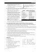
Table 2 Battery Bank Elements
Item Source of information
A. Load Size Site-specific
B. Daily Hours Site-specific
C. Days of Autonomy Site-specific
D. Application Site-specific
E. Conductor Efficiency Site-specific
F. Inverter Efficiency Inverter manufacturer
G. System Vdc Inverter manufacturer
H. Battery Vdc Battery manufacturer
I. Capacity Battery manufacturer
J. Maximum DoD Battery manufacturer