FX Inverter/Charger FX and VFX Mobile Series Installation Manual
About OutBack Power Technologies OutBack Power Technologies is a leader in advanced energy conversion technology. OutBack products include true sine wave inverter/chargers, maximum power point tracking charge controllers, and system communication components, as well as circuit breakers, batteries, accessories, and assembled systems.
Table of Contents Introduction ..................................................................................................... 5 Audience ......................................................................................................................................................................................... 5 Symbols Used .......................................................................................................................................................................
Table of Contents List of Tables Table 1 Table 2 Table 3 Table 4 Table 5 Table 6 Components and Accessories .................................................................................................. 8 Battery Bank Elements .......................................................................................................... 11 Ground Conductor Size and Torque Requirements ............................................................... 16 DC Conductor Size and Torque Requirements ..............
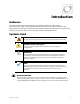
Introduction Audience This book provides instructions for the physical installation and wiring of this product. These instructions are for use by qualified personnel who meet all local and governmental code requirements for licensing and training for the installation of electrical power systems with AC and DC voltage up to 600 volts. This product is only serviceable by qualified personnel.
Introduction Welcome to OutBack Power Technologies Thank you for purchasing the OutBack FX Mobile Series Inverter/Charger. This product offers a complete power conversion system between batteries, shore power, and generator. 12-, 24-, 32-, 36-, and 48-volt models Output power from 2.0 kVA to 3.
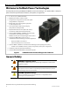
Introduction Models Sealed Mobile Models Sealed inverter models are designed for dusty and humid environments and can survive casual exposure to the elements. However, enclosed protection is still recommended. These inverters are internally ventilated and do not use outside air for cooling. To compensate, most sealed models are also equipped with the OutBack Turbo Fan assembly which uses external air to remove heat from the chassis. FX2012MT (2.0 kVA output, 12 Vdc) FX2024M (2.
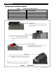
Introduction Components and Accessories Table 1 Components and Accessories Components to be Installed Accessories Included Battery Terminal Cover, red FX Mobile Series Installation Manual (this book) Battery Terminal Cover, black FX Mobile Series Operator’s Manual AC Plate “WARNING ELECTRICAL SHOCK” sticker DC Cover (DCC) or Turbo Fan Silicone Grease Packet Remote Temperature Sensor (RTS) DCC (DC Cover) This covers the DC terminal area on vented inverters.
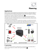
Planning Applications OutBack inverter/chargers are designed to use a battery bank to store energy. In shore-based mobile and marine connections, the shore power is used as the primary source. When the shore power is removed, the inverter takes over to run the loads from the batteries. The settings can be changed to accommodate many applications. Changes are made with the system display.
Planning Renewable Energy The inverter cannot connect directly to PV, alternators, or other DC sources. The batteries are the inverter’s primary source of power. However, if the DC sources are used to charge the batteries, the inverter can use their energy by drawing it from the batteries. A renewable source is always treated as a battery charger, even if all of its power is used immediately. The renewable source must have a charge controller, or some other regulation method, to prevent overcharging.
Planning E. Conductor efficiency: Wire size and other factors will waste power due to resistance and voltage drop. Typical acceptable efficiency is 96 to 99%. Any losses are essentially amp-hour capacity that the system cannot use. The battery bank size can be increased to account for losses. F. Inverter efficiency: FX specifications list “Typical Efficiency” to help estimate operating loss. G. System DC voltage: Each inverter model requires a specific DC voltage to operate. H.
Planning EXAMPLE #2 A. Loads: 1 kW (1000 W) 1) A ÷ [E x F] 1000 ÷ (0.97 x 0.93) = 1108.5 W B. 2) 1÷G 1108.5 ÷ 48 = 23.1 Adc Hours of use: 3 C. Days of autonomy: 1 3) 2xB 23.1 x 3 = 69.3 Ahr D. Off-grid system (FX3048MT inverter) 4) [3 x C] ÷ J [69.3 x 1] ÷ 0.5 = 138.6 Ahr E. Conductor efficiency: 97% (0.97) 5) 4÷I 138.6 ÷ 148.8 = 0.93 (rounded to 1) F. Inverter efficiency: 93% (0.93) 6) [G ÷ H] x 5 [48 ÷ 12] x 1 strings = 4 batteries G. System voltage: 48 Vdc H.
Installation Location and Environmental Requirements Sealed (FX) models are resistant to water and other elements but are not designed for permanent outdoor installations. If installation on the outside of a vehicle is required, the FX inverter must be installed under cover and protected from direct exposure to the environment. Vented (VFX) models are not resistant to water and other elements. They must be installed in a weather-proof enclosure or enclosed area.
Installation Mounting One person can install the FX inverter, but installation may be easier with two people. The unit has four mounting holes, one in each corner. Use fasteners in all corners for a secure installation. IMPORTANT: Use correct fasteners to secure the inverter to the mounting surface, regardless of the type of surface. OutBack cannot be responsible for damage to the product if it is attached with inadequate fasteners.
Installation Terminals and Ports DC and AC GROUND TERMINALS DC TERMINALS These terminals connect to the battery cables and the DC system. See page 18 for instructions. These terminals connect to a grounding system for both batteries and AC. See page 15 for instructions. CONTROL WIRING TERMINAL BLOCK These terminals receive control wires for a variety of functions including generator control. See pages 24 and 25 for instructions and the Operator’s Manual for more information.
Installation Wiring It will be necessary to remove knockouts from the AC Plate to run wires. The AC Plate has one knockout of ½” size and two knockouts of ¾” size. Install appropriate bushings to protect the wires. Use copper wire only. Wire must be rated at 75°C or higher. Grounding WARNING: Shock Hazard Mobile models perform automatic neutral-to-ground bond switching. When this function is engaged, the chassis ground is electrically common with the output neutral conductor.
Installation The inverter’s DC ground is a box lug located next to the negative DC battery terminal. This lug accepts up to 1/0 AWG (70 mm2 or 0.109 in2) wire. Local codes or regulations may require the DC ground to be run separately from the AC ground. Also, if present, it will be necessary to remove the DC Cover or Turbo Fan before making the ground connection. (See page 20.) Box Lug Figure 6 DC Ground Lug One ground terminal is labeled CHASSIS GROUND.
Installation DC Wiring WARNING: Shock Hazard Use caution when working in the vicinity of the inverter’s battery terminals. CAUTION: Equipment Damage Never reverse the polarity of the battery cables. Always ensure correct polarity. CAUTION: Fire Hazard The installer is responsible for providing overcurrent protection. Install a circuit breaker or overcurrent device on each DC positive (+) conductor to protect the DC system.
Installation To install DC cables and hardware: 1. Install all DC cables. Do not install hardware in a different order from Figure 8. The battery cable lug should be the first item installed on the stud. It should make solid contact with the mounting surface. Do not close the main DC disconnect until wiring is complete and the system is prepared for commissioning. M8 x 1.
Installation DC Cover or Turbo Fan Attachment COVER ATTACHMENT FX inverters are equipped with either the DC Cover or the Turbo Fan. To attach either cover, put the cover in place. Insert a screw at each corner using a Phillips screwdriver. As part of attaching the Turbo Fan, follow the wiring instructions in Figure 11. Figure 10 DC Cover Attachment TURBO FAN WIRING Install the wires in the AC Wiring Compartment to make the Turbo Fan operational.
Installation AC Wiring WARNING: Shock Hazard All AC source neutral and ground conductors should be mechanically bonded. The inverter’s neutral and ground conductors should be left isolated. The inverter performs automatic neutral-ground bond switching during operation. Ground fault circuit interrupter (GFCI) devices must be installed in a recreational vehicle wiring system to protect all branch circuits.
Installation AC Sources The inverter has a single set of AC terminals which are intended to connect to a single AC source. It cannot be directly wired to more than one AC source at the same time. If multiple sources are used, it is usually required to have a selector switch that changes from one to the next. The switch should be the “break before make” type which disconnects from one source before contacting another. It must also be a double-pole type which switches both the hot and neutral wires.
Installation ON and OFF Wiring The INVERTER ON/OFF jumper bridges two pins. The ON/OFF jumper parallels the two INVERTER ON/OFF terminals on the Control Wiring Terminal Block. If either set of connections is closed, the inverter is ON. Because the jumper is factory-installed, the inverter usually remains ON unless given a command by the system display. Jumper Off Jumper On Removing the jumper will turn the inverter OFF. This requires long-nose pliers or a similar tool.
Installation AUX Wiring The AUX+ and AUX– terminals are a switched 12 Vdc supply. The AUX can respond to different criteria and control many functions. These include cooling fans, vent fans, load diversion, fault alarms, and the Advanced Generator Start (AGS) function. The terminals can supply up to 0.7 amps at 12 Vdc (8.4 watts). This is sufficient to drive a small fan or a relay controlling a larger device. The terminals accept wire up to #14 AWG (2.5 mm2).
Installation Generator Control The AUX terminals can provide a signal to control an automatic-start generator. The control function can be Advanced Generator Start (AGS), which is situated in the system display. AGS can start the generator using settings from the system display, or it can use battery readings from the FLEXnet DC battery monitor. Alternately, the control function can be Gen Alert, which is a simpler function based directly in the FX inverter.
Installation Three-Wire-Start A “three-wire-start” generator has two or more starting circuits. It usually has a separate switch or position for cranking the generator. A three-wire generator has fewer automated functions than a two-wire. It usually requires multiple controls for starting, running, or stopping. The AUX terminals cannot control this type of generator without using a three-wire to two-wire conversion kit. Atkinson Electronics (http://atkinsonelectronics.
Installation AC Configurations Single-Inverter When installing an inverter AC system, the following rules must be observed. All overcurrent devices must be sized for 30 Aac or less. All wiring must be sized for 30 Aac or more. All output circuit breakers must be sized appropriately for loads and inverter power. The AC input (generator or utility grid) must be a single-phase source of the proper voltage and frequency.
Installation Multiple-Inverter AC Installations (Stacking) Installing multiple inverters in a single AC system allows larger loads than a single inverter can handle. This requires stacking. Stacking inverters refers to how they are wired within the system and then programmed to coordinate activity. Stacking allows all units to work together as a single system. Examples of stacking configurations include “classic series”, “OutBack series”, “parallel”, “series/parallel”, and “three-phase” configurations.
Installation There are two types of slave modes. The names used here are derived from their references onscreen. A “classic” slave is used for stacking when the slave operates semi-independently of the master. Although the master sets the phase relationship, the slave creates an output independent of the master. It is not possible to balance the outputs with the FW-X240 transformer using this method.
Installation Stacking Configurations Classic Series Stacking (Dual-Stack) In series stacking, two inverters create two separate 120 Vac output phases. One inverter is the master. The other is a slave that is intentionally 180° out of phase with the master. Each of these outputs can be used to power a separate set of 120 Vac loads. Collectively they form a “split-phase” configuration which produces 240 Vac. “Classic” series stacking is the simplest way to achieve this output.
Installation AC Source (Shore Power or AC Generator) AC Conduit Box System Display HUB 10.
Installation OutBack Series Stacking (Dual-Stack) In OutBack’s unique series stacking, two inverters create a “split-phase” configuration. This configuration creates two separate 120 Vac output legs. One output is the master. The other is a slave that is intentionally 180° out of phase with the master. The collective voltage is 240 Vac, as in Classic stacking. However, the output loads are balanced with the FW-X240 autotransformer.
Installation AC Source (Shore Power or AC Generator) AC Conduit Box System Display HUB 10.
Installation Parallel Stacking (Dual-Stack and Larger) In parallel stacking, two or more inverters create a single, common 120 Vac bus. All inverters share a common input (AC source). The inverters run loads on a common output bus. The master inverter provides the primary output. The slaves are connected to the same output and assist the master. The slave outputs are controlled directly by the master and cannot operate independently. Slave inverters can go into Power Save mode when not in use.
Installation AC Source (Shore Power or AC Generator) System Display LEGEND Hot L1 Neutral HUB 10.
Installation Series/Parallel Stacking (Quad-Stack or Larger) In series/parallel stacking, inverters use OutBack series stacking create separate 120 Vac output phases and 240 Vac collectively. However, in this configuration, each output has parallel inverters. One output contains the master; the other uses a slave. Each output has at least one additional slave. The 120 Vac loads on each output can exceed the size of a single inverter. They can be powered by all the inverters on that output.
Installation AC Source (Shore Power or AC Generator) System Display LEGEND Hot L1 Hot L2 Neutral HUB 10.
Installation Three-Phase Stacking In three-phase stacking, inverters create three separate 120 Vac output phases in a wye configuration. The output of each inverter is 120° out of phase from the others. Any two outputs produce 208 Vac between them. The outputs can be used to power three-phase loads when all inverters work together. The 120 Vac loads on each output cannot exceed a given inverter’s wattage. The other outputs cannot assist.
Installation AC Source (Shore Power or AC Generator) System Display HUB 10.
Installation NOTES: 40 900-0197-01-00 Rev A
Commissioning Functional Test WARNING: Shock Hazard and Equipment Damage The inverter’s AC and DC covers must be removed to perform these tests. The components are close together and carry hazardous voltages. Use appropriate care to avoid the risk of electric shock or equipment damage. It is highly recommended that all applicable steps be performed in the following order. However, if steps are inapplicable, they can be omitted.
Installation Figure 32 AC Terminals 4. Using a DVM or voltmeter, measure between the AC HOT OUT and AC NEUTRAL OUT terminals. (See Figure 32.) The inverter is working correctly if the AC output reads within 10% of 120 Vac. Proceed past the items below to Step 5. To start a multiple-inverter (stacked) system: 1. Close the main DC circuit breakers (or connect the fuses) from the battery bank to the master inverter. The inverter will activate. Do not turn on any AC circuit breakers at this time.
Installation 8. Close the AC input circuit breakers and connect an AC source. Using a DVM or voltmeter, check the AC HOT IN and AC NEUTRAL IN terminals for 120 Vac from the AC source. If a system display is present, confirm that the inverter accepts the AC source as appropriate for its programming. (Some modes or functions may restrict connection with the source. If one of these selections has been used for the system, it may not connect.) Check the system display indicators for correct performance.
Installation Table 6 Terms and Definitions Term Definition CSA Canadian Standards Association; establishes Canadian national standards and the Canadian Electrical Code, including C22.1 and C22.
Index A AC Plate....................................................................................... 8 AC Sources ............................................................................... 22 AC Terminals ................................................................9, 15, 21 AC Test Points ......................................................................... 42 Adding New Devices ............................................................ 43 Advanced Generator Start (AGS) ...................
Index M Master (Stacking)...............................................28, 34, 36, 38 MATE, MATE2, MATE3...........................................6, 9, 23, 28 MATE/HUB Port ...................................................................... 23 MATE3 ....................................................................................... 44 Models ......................................................................................... 7 Mounting .........................................................
This page intentionally left blank.
Masters of the Off-Grid.™ First Choice for the New Grid. Corporate Headquarters 17825 – 59th Avenue N.E. Suite B Arlington, WA 98223 USA +1.360.435.6030 900-0197-01-00 Rev A European Office Hansastrasse 8 D-91126 Schwabach, Germany +49.9122.79889.