
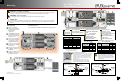
Quick Start Guide


Neutral
Ground
AC IN
MATE RTS
CB3
CB2
CB1
CB6
CB5
CB4
CB8
CB7
CB1
0
CB9
CB1
2
CB1
1
CB1
4
CB1
3
CB1
6
CB1
5
GND
I/ON
I/ON
I/ON I/ONI/ONI/ON
NORMAL
UP
DOWN
BYPASSE
D
O/OFFO/OFF
GND
DC
NEGATIVE
SHUNT A
SHUNT C
SHUNT B
AC IN
DC
AC OUT
AC IN
DC
AC OUT
MATE RTS
AC HOT OUT
AC NEUTRAL OUT
CHASSIS GROUND/PE
CHASSIS GROUND/PE
AC NEUTRAL IN
AC HOT IN
MATE RTS
AC HOT OUT
AC NEUTRAL OUT
CHASSIS GROUND/PE
CHASSIS GROUND/PE
AC NEUTRAL IN
AC HOT IN
MASTER
BYPASS
SLAVE L2
BYPASS
MASTER
OUTPUT
SLAVE L2
OUTPUT
MASTER
INPUT
SLAVE L2
INPUT
250
ON
250
ON
OFF
O
SLAVE L2
INVERTER
MASTER
INVERTER
FNDC
OFF
O
OFF
O
Charge
Controller
OFF
O
O
F
F
O
FAULT
PV
INACTIVE
NORMAL
PV ACTIVE
PV ARRAY
GROUND
FAULT
DETECTOR
INTERRUPTER
GROUND
FAULT
PV
ARRAY
General Wiring
O
I
O
I
O
I
O
I
O
I
O
I
O
I
O
I
O
I
O
I
O
I
O
I
AC
Source
Ground Electrode
System (Ground Rod)
900-0158-01-00 REV B.vsd
©2013 OutBack Power Technologies. All Rights Reserved.
PV Array #1
Battery Bank
Vented Battery Enclosure
AC
Distribution Panel
PV Array #2
PV Combiner Box
Charge
Controller #1
Charge
Controller #2
DC
POSITIVE
Negative
Positive
Ground
DC
LEGEND
IMPORTANT: Example only.
Actual wiring may vary depending on local
electric code. Factory wiring is not shown.
Master
Inverter
Slave
Inverter
Charge
Controller
MATE3
Ground
Electrode
Conductor
RTS
CAT5
Cable
PV
ARRAY
AC IN
NEUTRAL
GROUND
AC Subpanel
Loads
(230 Vac)
L1
N
N
Neutral
HOT L1
Ground
AC LEGEND
L1
N
L1
AC IN
AC OUT
AC
OUT
AC OUT