
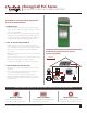
200 PLC Specification Sheet

2
OutBack reserves the right to make changes to the products and information contained in this document without notice.
Copyright © 2018 OutBack Power. All Rights Reserved. OutBack is a registered trademark of The Alpha Group.
EnergyCell PLC Front Terminal SPECIFICATIONS 03/2018
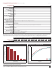
Discharge in Hours:
12V Ampere Hour Capacity to 1.75 Volts Per Cell at 77°F (25°C)
1 2 3 4 5 8 12 20 24 48 100
EnergyCell 200PLC
104 120 132 140 145 160 168 178 182 191 200
Cycle Life
Cycle Count
Depth of Discharge
8,000
7,000
6,000
5,000
4,000
3,000
2,000
1,000
0
10% 20% 30% 50% 80% 100%
Battery Characteristics—Capacity vs Temperature
% of Capacity
Temperature
105
100
95
90
85
80
75
70
65
60
55
50
-30°C -20°C -10°C 0°C 10°C 20°C 30°C 40°C
C/100
C/20
*
Consult local and regional electrical code for proper installation of energy storage requirements.
EnergyCell Models: 200PLC
Cells Per Unit
6
Nominal Voltage
12VDC
Cycle Life (50% DOD, 1.75VPC)
3000
Absorb Voltage (25°C)
1
14.1VDC
Absorb Time
2
6hrs (0.15C)
Float Voltage (25°C)
1
13.5VDC
Float Time
6hrs (0.15C)
Equalize Voltage and Charge Frequency
14.1
Re-Bulk Voltage
3
14.1
Re-Float Voltage
3
13.5
Maximum Charge Current (Per Battery)
40A
Operating Temperature Range
(w/Temperature Compensation)
Discharge: -40 to 149°F (-40 to 65°C) Charge: 5 to 140°F (-15 to 60°C) Storage: -4 to 104°F (-20 to 40°C)
Optimal Operating Temperature Range
68 to 86°F (20 to 30°C)
Temp-Comp Factor (Charging)
-4mV per °C per cell (2V)
Self-Discharge Time
Batteries can be stored up to 24 months at 25°C (77°F) before a freshening charge is required. For higher temperatures the time interval will be shorter
Terminal Type
T11
Terminal Hardware Initial Torque
11 to 14.7Nm
Weight (lb/kg)
130 / 59
Dimensions H x D x W (in/cm)
4
12.6 x 22 x 4.92 / 32 x 55.88 x 12.50
Warranty
5
Domestic: 6 year full replacement Global: 4-5 year full replacement
Accessories
Ships with interconnect bars, terminal covers and hardware kit
Note: PC-ABS ame retardant jar and cover to UL94V-0
1
If using both inverter and charge controller, set the charge controller to 0.4V higher (0.2V for 24V systems) to give the charge controller charging priority.
2
Will always be 2 hours if charge rate is 10%
of battery bank amp-hours. For higher or lower charge rates, use the formula AR ÷ (CR x 0.5) = absorb time where AR = amp-hours remaining after absorb voltage is first reached (10% of battery bank Ah) and Cr = amp-hours of current charge.
3
Default values for 12/24/48V systems. May need to be adjusted for site application.
4
Batteries to be installed with 0.5in (12.7mm) spacing minimum and free air ventilation.
5
See OutBack EnergyCell warranty document for full details.