
OutBackPower FXR Renewable Series 230V E Model Operator’s Manual
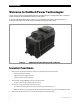
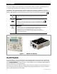

Table of Contents
6 900-0169-01-00 Rev B
List of Figures
Figure 1 FXR Series Inverter/Charger with Turbo Fan ......................................................................................... 8
Figure 2 MATE3 and AXS Port ................................................................................................................................... 10
Figure 3 LED Indicators ................................................................................................................................................ 11
Figure 4 Inverter Status LED Indicators .................................................................................................................. 12
Figure 5 Charging Stages Over Time ...................................................................................................................... 30
Figure 6 Charging Stages Over Time (24/7) ......................................................................................................... 30
Figure 7 Repeated Charging (1
st
and 2
nd
Cycles) ................................................................................................ 34
Figure 8 Repeated Charging (3
rd
, 4
th
, and 5
th
Cycles) ........................................................................................ 35
Figure 9 OutBack HUB10.3 and MATE3.................................................................................................................. 39
Figure 10 Example of Parallel Stacking Arrangement (Three Inverters)....................................................... 40
Figure 11 Example of Three-Phase Stacking Arrangement (Three Inverters) ............................................ 41
Figure 12 Example of Three-Phase Stacking Arrangement (Nine Inverters) .............................................. 41
Figure 13 Power Save Levels and Loads .................................................................................................................. 42
Figure 14 Power Save Priority (Parallel) ................................................................................................................... 44
Figure 15 Power Save Priority (Three-Phase) ......................................................................................................... 44
Figure 16 Home Screen .................................................................................................................................................. 51
Figure 17 Inverter Screens ............................................................................................................................................ 51
Figure 18 Battery Screen ................................................................................................................................................ 52
Figure 19 AC Test Points ................................................................................................................................................ 53
Figure 20 Temperature Derating ................................................................................................................................ 67