
OutBackPower FXR Renewable Series 230V E Model Operator’s Manual


Operation
44 900-0169-01-00 Rev B
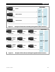
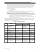
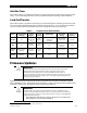
Figure 14 Power Save Priority (Parallel)
The fourth line shows that loads of 18 Aac or more (approximately 4 to 4.5 kW) are present on the system.
This load causes all four inverters to be activated.
The last line shows that the loads are reduced to 8 Aac. Since this load is distributed among four inverters,
the master reads 2 Aac, the lower threshold for Power Save. This causes one slave to enter Silent mode. The
8 Aac are distributed among the remaining three inverters. If the loads decreased to 6 Aac, a second slave
would go silent.
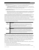
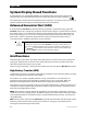
Figure 15 shows a system of six FXR2012E inverters. In this example the inverters have been stacked in
a three-phase system. The master inverter is on the Phase A output while subphase masters are on
Phase B and Phase C. Each master has one slave inverter.
The captions at the top indicate the ranking of each inverter.
The captions also show the port assignments on the communications manager. The Phase A inverters use
ports 1 and 2 However, the communications manager requires the Phase B and C inverters to use ports 4
and 5 and ports 7 and 8 respectively.
The notations at the bottom show how the slaves are activated as loads are applied. The load on Phase C is
not equal to the others, so the slave is not activated at the same time.
Figure 15 Power Save Priority (Three-Phase)
The third line shows that loads of varying size on all phases have caused all inverters to be activated.
The last line shows that the load on Phase B is reduced to 4 Aac. This causes the slave to go silent. The other
phases are not affected.
Master
Slave 1 Slave 3 Slave 2
Port 1
Master Power Save = 0
Port 2
Slave Power Save = 1
Port 4
Slave Power Save = 3
Port 3
Slave Power Save = 2
<6 Aac On Off Off Off
6 Aac On On Off Off
12 Aac On On On Off
18 Aac On On On On
8 Aac On On On Of
f
Master
Slave 1 Slave 1Sub
p
hase Master
Port 1
Master Power
Save = 0
Port 2
Slave Power
Save = 1
Port 5
Slave Power
Save = 1
Port 4
Master Power
Save = 0
Load (A) Load (B) Load (C)
5 Aac On Off 5 Aac On Off 5 Aac On Off
6 Aac On On 6 Aac On On 5 Aac On Off
12 Aac On On 8 Aac On On 10 Aac On On
12 Aac On On 4 Aac On Off 10 Aac On On
Sub
p
hase Master Slave 1
Port 7
Master Power
Save = 0
Port 8
Slave Power
Save = 1
Phase A Phase B Phase C