
OutBackPower FXR Renewable Series 230V E Model Operator’s Manual

Operation
900-0169-01-00 Rev B
43
Master Power Save Level
appears on an inverter which is set as master (the default setting). The range of
rank numbers is 0 to 10. The default value is 0. The master is normally left at this value.
The Master Power Save Level function is used for the master inverter on Port 1. It is also used for any
subphase masters in a three-phase system. The ranking of a subphase master is treated the same as the
master. If the master is set at 0, subphase masters should also be 0.
Slave Power Save Level
appears on an inverter which is set as slave. The range of rank numbers is 1 to 10.
(The default value for all ports is 1.)
When subphase master inverters are in use, the slaves for the additional phases are ranked identically to
the slaves on the master phase. If the master inverter has two slaves ranked 1 and 2, any other phases
should also rank their slaves 1 and 2. Slaves on multiple phases should not be ranked sequentially
(1 through 6 and so on). This would cause delays in output.
The ranks are prioritized so that lower-numbered ranks turn on sooner and higher ranks turn on later.
The lowest-ranked inverter does not go silent and remains on unless ordered otherwise. The
lowest-ranked inverter is expected to be the master. The priorities are the same across both screens.
If Port 1 (master) is set at 0 and Port 2 (slave) is set at 1, the slave will turn on later. Since the
Master
item is the only one that goes to 0, it is easy to ensure that all slave inverters go silent.
Subphase master inverters are set at 0 because all phases must have at least one inverter that does not
enter Silent mode. The slaves for each phase are set identically to each other so that all phases receive
additional power at the same time as needed.
IMPORTANT:
Set the master (or subphase) rank at 0 and arrange the slave ranks in order (1, 2, 3, 4, etc.).
Another order may defeat the purpose of Power Save mode. Leaving the master at 0 makes
power available from the master; the other inverters should not be active. If a slave is ranked
lower (prioritized higher) than the master, that slave will not go silent.
NOTE:
Disregard this rule if the installation requires some slaves to be continuously active.
IMPORTANT:
Do not give slave inverters the same rank numbers. If, for example, multiple slaves were all
ranked at 1, they would all come on at the same time. Once they came on, the divided load
would cause the master to detect a minimal load on its output, so it would shut off all the slaves,
at which point the master would read a high load again. This could quickly escalate into a rapid
on/off cycling of inverters and could cause long-term system problems.
NOTE
: Power Save is used by the battery chargers of stacked systems with slave inverters. Not all
chargers are activated immediately. Initially the master is the only active charger. The batteries will
absorb current up to the maximum for all chargers. When the batteries (and the master) draw more
than 6 Aac, the master will turn on the first slave charger. The batteries will absorb that additional
current and more. The master will then turn on more slaves until all active chargers are operating.
If the master
Charger AC Limit
is reduced below 6, it will not turn on any slaves and will remain the
only charger. For more information on charging with stacked inverters, see page 29. If other
adjustments are required to the maximum charge rate, see page 69.
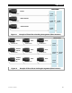
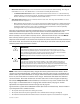
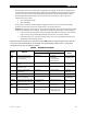
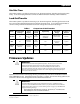
Figure 14 shows a system of four FXR2012E inverters (the master and three slaves). These inverters in
a parallel system with a common load bus.
The captions at the top indicate the ranking of each unit.
The captions also show the port assignments on the communications manager (1 through 4).
The notations at the bottom show how the units are activated in sequence as loads of 6 Aac are applied.