
OutBackPower FXR Renewable Series 230V E Model Operator’s Manual

Operation
42
900-0169-01-00 Rev B
Power Save
Each FXR inverter consumes 34 watts of idle power while it remains on, even if it is not actively
inverting or charging. The Power Save function allows the option to put part of a parallel system into
a quiescent state known as Silent mode. This mode minimizes the idle consumption. The inverters
will come on again when the loads require power. (The term “Silent” is also used in an unrelated
context during battery charging. See page 32.)
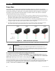
When the load increases by 6 Aac, the master inverter activates an additional slave inverter for assistance.
When the load decreases to 2 Aac or less (as detected by the master), the slave is deactivated and returns to
Silent mode. Each additional load increments of 6 Aac activates an additional slave.
The order in which slaves activate (or return to Silent mode) is controlled by programming in the system
display. The inverters are given a “rank”, or level number. Lower rank numbers activate when lesser loads
are applied. Higher ranks only activate when the load increases to a high level.
The lowest-ranked inverters do not enter Silent mode. This includes the master and subphase masters.
They remain active unless specifically turned off. These inverters can still enter Search mode.
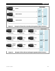
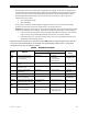
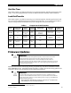
Figure 13 Power Save Levels and Loads
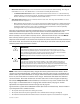
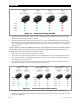
The actual watt and ampere thresholds for activating each model are depicted on the following pages.
IMPORTANT:
I
t is highly recommended to use the MATE3 Configuration Wizard to set up this function. It is
essential to set the slave Power Save Levels in sequential order. Failure to set them up correctly will
cause erratic system performance. The Configuration Wizard automatically programs the correct
priorities. (See the MATE3 owner’s manual.)
To set these items manually without the Configuration Wizard:
In the MATE3 system display, the
Power Save Ranking
screen uses
Power Save Level
selections to
assign ranks to the inverter on each port. The screen reads
Master Power Save Level
or
Slave Power
Save Level
, depending on the inverter’s stacking designation.
The stacking designations also control which ports are used on the HUB10.3 communications
manager. The master inverter must be plugged into port 1. In parallel stacking, any slave inverter can
use any other port, beginning with port 2. In three-phase stacking, the port assignments are very
specific, as illustrated in the HUB10.3 literature.
Master
Slave 1 Slave 3Slave 2
Off
Off Off
On
Off Off
On
On Off
On
On On
On
On
On
Increasing load
Minimal load
High load
On
Maximum load