INTERNATIONAL FX/VFX SERIES INVERTER/CHARGER FX2012ET FX 2024ET FX2348ET VFX2612E VFX3024E VFX3048E Installation Manual Mounting and Installation
Warranty Introduction Dear OutBack Customer, Thank you for your purchase of OutBack products. We make every effort to assure our power conversion products will give you long and reliable service for your renewable energy system. As with any manufactured device, repairs might be needed due to damage, inappropriate use, or unintentional defect. Please note the following guidelines regarding warranty service of OutBack products: • Any and all warranty repairs must conform to the terms of the warranty.
TABLE OF CONTENTS EU Declaration of Conformity......................................................................................................................................................2 Welcome to the OutBack Power Systems FX Series Inverter/Charger System .............................................3 FX Series Inverter/Charger Models ...........................................................................................................................................3 Safety...............
EU DECLARATION OF CONFORMITY According to ISO / IEC Guide 22 and EN45014 Product Type: Inverter/Charger Product Model Numbers: • FX2012ET • FX2024ET • FX2348ET • VFX2612E • VFX3024E • VFX3048E The OutBack Power Systems FX Series Inverter/Chargers export (“E”) models comply with the following EU directives when installed in off-grid applications only: • EU Declaration of Conformity regarding Electromagnetic Compatibility 89/336/EEC (“Council Directive of 3 May 1989”) • Low Voltage Directive 73/23/EEC (“Coun
Welcome to the OutBack Power Systems FX Series Inverter/Charger System The FX Series Inverter/Charger offers a complete power conversion system—DC to AC, battery charging, and an AC transfer relay—and can be used as a stand-alone or back-up application. It is designed for indoor or enclosed locations. OutBack Power Systems does everything possible to assure the components you purchase will function properly and safely when installed as instructed according to local and national electrical codes.
READ FIRST! IMPORTANT SAFETY INSTRUCTIONS SAVE THESE INSTRUCTIONS Read all instructions and cautionary markings on the FX, the batteries and all appropriate sections of this installation and user manual as well as other component manuals before using the system. Be cautious around electricity, electrical components, and batteries. Shocks, burns, injury, and even death can occur if an installer comes in contact with electricity.
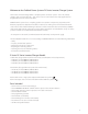
WARNING: WORKING NEAR LEAD ACID BATTERIES CAN BE DANGEROUS. BATTERIES GENERATE EXPLOSIVE GASES DURING NORMAL OPERATION. Design the battery enclosure to prevent accumulation and concentration of hydrogen gas in “pockets” at the top of the enclosure. Vent the battery compartment from the highest point to the outside. A sloped lid can also be used to direct the flow of hydrogen to the vent opening.
SYSTEM PROTECTION Electrical systems are designed to protect you, the wires, the components, and the devices served by the system. Each FX must be part of a permanently grounded electrical system (see page 9). Grounding protects people and equipment from electrical shock. Grounding must be done according to local and national electrical codes. OutBack circuit breakers—rated at 100% duty cycle— protect wiring by limiting the amount of current entering a system.
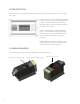
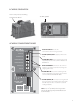
AC WIRING ORIGINATION Lexan cover protects AC Wiring Compartment Board AC Wiring Board AC WIRING COMPARTMENT BOARD AC Terminal Block secures AC connections to the FX using set screws AC HOT OUT AC HOT (PHASE) OUT supplies power to the loads. AC NEUTRAL OUT AC NEUTRAL OUT acts as neutral leg for loads supplied by the FX and is common with the AC NEUTRAL IN. CHASSIS GROUND/PE CHASSIS GROUND/PE CHASSIS GROUND connections are common and act as grounds for both the incoming and outgoing AC circuits.
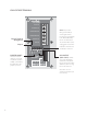
LOW VOLTAGE TERMINALS AC HOT OUT AC NEUTRAL OUT NOTE: Keep Control Wiring Terminal Block screws tight and the block itself secured tightly to AC Board. Otherwise, the FX can malfunction. The Terminal Block can be unplugged for easier wire installation and removal/ reinstallation of the FX.
AC AND DC GROUNDING REQUIREMENTS • Connect only to a grounded, permanent wiring system. Ensure there is only one neutral-ground connection in the system at any time. Some codes require this connection be made at the main panel only. • Some generators have their own neutral ground connection. If a generator is used, its neutralground connection will need to be disengaged for proper system operation.
FX PARTS AND ACCESSORIES BATTERY TERMINAL COVERS AC CONDUIT PLATE* • AC conduit connects to the AC Conduit Plate for installations which do not utilize an optional ACA. • The caps are made of stiff plastic with a snap-on design; remove them carefully using a flat-blade screwdriver inserted into the slots on the sides of each cover. • DC conduit may be required for exposed installations. • The DCA cover option (see below) allows conduit connection. • Always keep the battery terminal covers installed.
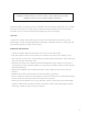
.02” (33.07 CM) SIDE VIEW 8.25” (20.95 CM) 22” (55.99 CM) TOP VIEW Weight is approximately 56 lbs (25.40 kg) MOUNTING • The E Series FX Series Inverter/Charger is approved for indoor or enclosed protected mounting only. • An FX weighs approximately 56 lbs (25.40 kg) and must be secured with appropriate fasteners to a sturdy mounting surface capable of supporting its weight. It is easier for two people to install the FX due to its weight.
WIRE CONNECTIONS NOTE: A system’s individual voltage requirements (230 or 3-phase) as well as how each FX is to function all determine how the FXs are wired. Each FX must be wired to the logical leg or phase of the system. Each FX must be programmed or “stacked” according to this phase. Please see the International FX and VFX Series Inverter/Charger Programming Manual before connecting any wires to or from the FX. AC Follow these steps to wire the FX to your system: 1.
Battery Wiring Examples In renewable energy systems, batteries are connected to each other in one of three ways: SERIES • Series (voltage increases, amperage stays the same as a single battery) • Parallel (voltage stays the same as a single battery, amperage increases) • Series/Parallel (both voltage and amperage increase) + + - - + 12V/200 Amp Hours 12V/200 Amp Hours PARALLEL 12V + 12V + 12V + 12V = 48 V + + - - Voltage remains at 12V SERIES/PARALLEL + - 12V/200 Amp Hours - 12V/200 Am
6V Battery Wiring Examples - 6 VOLT 6 VOLT DC DISCONNECT (FUSE OR CIRCUIT BREAKER) SERIES/12 VOLT FX 12 VOLT INVERTER/CHARGER - 6 VOLT 6 VOLT SERIES STRING 1 CONNECTS TO INVERTER/CHARGER’S POSITIVE TERMINAL SERIES STRING 1 - 6 VOLT 6 VOLT SERIES STRING 2 DC DISCONNECT (FUSE OR CIRCUIT BREAKER) - 12 VOLT INVERTER/CHARGER 14 SERIES/PARALLEL/12 VOLT FX
- 6 VOLT 6 VOLT - 6 VOLT 6 VOLT DC DISCONNECT (FUSE OR CIRCUIT BREAKER) - SERIES/24 VOLT FX 24 VOLT INVERTER/CHARGER - 6 VOLT 6 VOLT - 6 VOLT 6 VOLT SERIES STRING 1 SERIES STRING 1 CONNECTS TO INVERTER/CHARGER’S POSITIVE TERMINAL - 6 VOLT - - 6 VOLT 6 VOLT 6 VOLT SERIES STRING 2 DC DISCONNECT (FUSE OR CIRCUIT BREAKER) - SERIES STRING 2 CONNECTS TO INVERTER/CHARGER’S NEGATIVE TERMINAL SERIES/PARALLEL/24 VOLT FX 24 VOLT INVERTER/CHARGER 15
- 6 VOLT 6 VOLT 6 VOLT 6 VOLT - - - 6 VOLT - - 6 VOLT 6VOLT 6 VOLT DC DISCONNECT (FUSE OR CIRCUIT BREAKER) SERIES/48 VOLT FX 48 VOLT INVERTER/CHARGER 16
12V Battery Wiring Examples - 12 VOLT 12 VOLT DC DISCONNECT (FUSE OR CIRCUIT BREAKER) - 24 VOLT INVERTER/CHARGER - 12 VOLT SERIES/24 VOLT FX - 12 VOLT 12 VOLT DC DISCONNECT (FUSE OR CIRCUIT BREAKER) - 12 VOLT INVERTER/CHARGER PARALLEL/12VOLT FX 17
- 12 VOLT 12 VOLT - 12VOLT 12 VOLT DC DISCONNECT (FUSE OR CIRCUIT BREAKER) - SERIES/48 VOLT FX 48 VOLT INVERTER/CHARGER - 12 VOLT 12 VOLT SERIES STRING 1 CONNECTS TO INVERTER/CHARGER’S POSITIVE TERMINAL SERIES STRING 1 - 12 VOLT 12 VOLT SERIES STRING 2 DC DISCONNECT (FUSE OR CIRCUIT BREAKER) SERIES/PARALLEL/24 VOLT FX 24 VOLT INVERTER/CHARGER 18
- 12 VOLT 12 VOLT - 12 VOLT 12 VOLT SERIES STRING 1 SERIES STRING 1 CONNECTS TO INVERTER/CHARGER’S POSITIVE TERMINAL - 12 VOLT - - 12 VOLT 12 VOLT 12 VOLT SERIES STRING 2 DC DISCONNECT (FUSE OR CIRCUIT BREAKER) - SERIES STRING 2 CONNECTS TO INVERTER/CHARGER’S NEGATIVE TERMINAL 48 VOLT INVERTER/CHARGER SERIES/PARALLEL/48 VOLT FX 19
AC WIRING NOTES AC HOT (PHASE) OUT • Supplies the AC hot output conductors through a 30 amp maximum AC branch rated circuit breaker using 6 AWG (16.0 mm2) wire and connect to the AC AC NEUTRAL OUT/AC NEUTRAL IN • Connects the AC neutral input conductor to the AC NEUTRAL IN terminal. • Connects the AC neutral output conductor to the AC NEUTRAL OUT terminal.
LOW-VOLTAGE WIRING This six-position terminal block can be unplugged to make wiring easier and to simplify the removal and reinstallation of an FX. It must be securely and completely plugged in for proper FX functioning. Otherwise, operational errors can occur.
Prior to installing an ON/OFF switch, if the FX’s AC output is off, check that the jumper is present and well-connected before installing a switch. You want to confirm the system is in good working order. Suggested switches include push on/push off style. Should you decide to install an OutBack MATE at a later date, bear in mind the installed switch overrides the control provided by the MATE if the switch is set to OFF. If the switch is set to ON, the MATE will function normally and control the inverter(s).
RTS, MATE/HUB WIRING RJ-11 modular jack connects the RTS, the external battery temperature sensor. RJ-45 jack is used for external communications. • RJ-11 modular jack connects RTS, the optional external battery temperature sensor.* • RJ-45 jack connects MATE or HUB to FX using CAT5 cable.** AC HOT OUT AC NEUTRAL OUT *When a HUB is used, plug the RTS into the Master FX, which should be plugged into HUB’s Port 01.
24 GREEN BLUE BROWN BROWN BLUE GREEN GROUND TBB 30 AMP INPUT BREAKER AC NEUTRAL IN CHASSIS GROUND AC HOT IN AC SOURCE BLUE BROWN BROWN BROWN 30 AMP OUTPUT BREAKER BROWN MECHANICAL INTERLOCK 30 AMP BYPASS BREAKER All cables must be 10 AWG (6.0 mm2 ) 1. All cables are to be or larger 8AWG THHN or larger.
PARALLELED DUAL FX SYSTEM • All AC wiring from the AC source and to the AC loads must collectively handle 60 amps AC or more. • All other AC wiring capacity must equal 30 amps AC. • A paralleled dual FX system can continuously power 4-6kW of loads depending on which model is used. (16.0 mm2) NOTE: Program the lowest-installed FX as Master (1-2ph MASTER) and the second FX as an OutBack L1 Slave (OB SLAVE L1). The Master FX must be plugged into Port 1 of the HUB.
PARALLELED QUAD FX SYSTEM • • • • All AC wiring from the AC source and to the AC loads must collectively handle 100 amps AC or more. All other AC wiring must handle a capacity of 30 amps AC. This system can continuously power 8-12kW of loads depending on which model is used. Connecting more load than the continuous rating of the FX may cause breakers to trip or the FX to shut off its AC output.
(16.
(16.
GENERATOR AUTO START The following schematic shows how to hook up a relay that interfaces with the two-wire start generator. Three-wire start generators require an adapter like the Atkinson GSCM available at www.atkinsonelectronics.com. TWO WIRE START GENERATOR HOOK UP GENERATOR 12V RELAY INVERTER NC COM COIL ON/OFF NO AUX + AUX XCT XCT + Most 12V relays will work for generator starting. Select one between 5 and 30 amp contacts. Relays with gold-plated contacts are recommended.
INSTALLATION CHECK LIST ITEM All manuals read and reviewed? FX OutBack Charge Controller MATE HUB System mounted with the recommended number and sized fasteners? System installed according to local codes? System inspected? System permanently grounded? Did the installer use OutBack recommended wire type and gauge adjusted for temperature ratings and length? All AC wiring rated for 75° C or higher? Battery cables rated 75° C or higher? 6.0 mm2 (10 AWG) wire used for AC Input Hot? 6.
APPENDIX RATINGS FX2012ET Nominal DC Input Voltage Range 12VDC Nominal AC Voltage / Frequency 230VAC / 50 HZ Continuous Power Rating at 25C Ambient 2000VA Continuous AC RMS Output at 25°C 8.
FX2348ET Nominal DC Input Voltage Range 48VDC Nominal AC Voltage / Frequency 230VAC / 50 HZ Continuous Power Rating at 25C Ambient 2300VA Continuous AC RMS Output at 25°C 10.0 Amps AC Idle Power - Full AC Output ≈ 23 Watts DC Idle Power - Search Mode 6 Watts DC Typical Efficiency 93.
VFX3024E Nominal DC Input Voltage Range 24VDC Nominal AC Voltage / Frequency 230VAC / 50 HZ Continuous Power Rating at 25C Ambient 3000VA Continuous AC RMS Output at 25°C 20 Amps AC Idle Power - Full AC Output ≈ 20 Watts DC Idle Power - Search Mode 6 Watts DC Typical Efficiency 90% Total Harmonic Distortion - Typical 2% Output Voltage Regulation ± 2% Maximum Output Current – Peak (1 mSec) 35 amps AC Maximum Output Current - RMS (100 mSec) 25 amps AC AC Overload Capability - Surge 5750
RATINGS DETAILED NOMINAL AC OUTPUT VOLTAGE OF AN FX SYSTEM Single Phase Parallel Stacked 230VAC at 50 Hz 230VAC at 50 Hz on one AC output leg Three Phase Stacked 230VAC at 50 Hz per AC output leg (limit three) / 400VAC at 50 Hz between AC output legs RECOMMENDED FX DC VOLTAGE RANGE NOTE: The last two digits in the model number designate the nominal DC voltage. Example: FX2024ET = 24V DC Voltage.
RATED DC CHARGING CURRENT NOTE: This is the maximum continuous DC current that the FX can send to the batteries when charging. FX2012ET FX2024ET FX2348ET VFX2612E VFX3024E 100ADC (ADC = Amps DC) 55ADC 35ADC 120ADC 85ADC VFX3048E 42ADC AC INPUT OPERATING VOLTAGE RANGE NOTE: This is the recommended AC input voltage range to be supplied to the FX. Voltages outside of this range may damage AC loads connected to the FXs AC output terminals.
MAXIMUM AND DEFAULT AC INPUT AND DC CHARGER (bulk stage) OUTPUT VALUES FX2012ET FX2024ET FX2348ET VFX2612E VFX3024E VFX3048E AC Max = 6AAC (Default = 5 AAC) AC Max = 7AAC (Default = 5 AAC) AC Max = 7AAC (Default = 5 AAC) AC Max = 7AAC (Default = 6 AAC) AC Max = 10AAC (Default = 9 AAC) AC Max = 10AAC (Default = 9 AAC) DC Max = 100ADC DC Max = 55ADC DC Max = 35ADC DC Max = 120ADC DC Max = 85ADC DC Max = 45ADC AC INPUT FREQUENCY RANGE NOTE: If the AC input source is out of the range noted below, the FX will
MAXIMUM OVERCURRENT PROTECTION AMPACITY This rating specifies the proper overcurrent protection ampacity. • • • • • OBDC breakers are panel-mount circuit breakers. Class T DC fuses are terminal-mounted and should always be used in conjuncture with a disconnect mechanism. FXs used in home installations should use properly sized DC circuit breakers. A DC breaker includes both overcurrent protection and disconnect capability.
Recommended Wire Sizes FX Model Max DC Amps NEC Max Amps x 1.25* 2% Voltage Drop Ohms Allowed OutBack Suggested Cables Max Battery Cable Length** (Positive + Negative) FX2012ET 200 250 0.24 0.001200 4/0 250 20’ FX2024ET 125 156.25 0.48 0.003840 2/0 175 30’ VFX3024E 150 187.5 0.48 0.003200 4/0 30’ FX2348ET 57.5 71.875 0.96 0.016696 1/0 30’ VFX2612E 260 325 0.24 0.000923 4/0 15’ VFX3048E 75 93.75 0.96 0.
12 VDC System DEFAULT MINIMUM MAXIMUM Float Voltage 13.6V 12V 15V Absorb Voltage 14.4V 13V 16V EQ Voltage 14.4V 14V 17V ReFloat 12.5V 11V 13V LBCO 10.5V 9V 12V LBCI 12.5V 10V 14V Sell RE 13V 10V 15V 14V 12V 18V Gen Alert Off Set Point On Set Point 11V 10V 14V Load Shed Off Set Point 11V 10V 14V Vent Fan ON Set Point 13V 10V 16V Diversion ON Set Point 14.6V 12V 16V Absorb Time 1.0 hours 0.0 hours 24.0 hours EQ Time 1.0 hours 0.0 hours 24.
TWO YEAR LIMITED WARRANTY INFORMATION FX Series Inverter/Charger Products OutBack Power Systems, Inc. (“OutBack”) provides a two year (2) limited warranty (“Warranty”) against defects in materials and workmanship for its FX/VFX Series Inverter/Charger products (“Product(s)”) if installed in fixed location applications. The term of this Warranty begins on the Product(s) date of manufacture or the initial purchase date as indicated on the warranty registration card submitted to OutBack, whichever is greater.
To request warranty service, you must contact OutBack Technical Services at (360) 435-6030 or support@ outbackpower.com within the effective warranty period. OutBack Technical Support will attempt to troubleshoot the product and validate that the failure is product related. If warranty service is required, OutBack will issue a Return Material Authorization (RMA) number. A request for an RMA number requires all of the following information: 1.
Limited Warranty Registration Complete this form to request a Limited Warranty, and return it to: Outback Power Systems Inc. 19009 62nd Ave. NE Arlington, WA 98223 NOTE: Please submit a copy (not the original) of the Product purchase invoice, which confirms the date and location of purchase, the price paid, and the Product Model and Serial Number.
43
44
Corporate Headquarters 19009 62nd Avenue NE Arlington, WA 98223 USA Phone: (+1) 360.435.6030 www.outbackpower.com European Sales Office C/ Castelló, 17 08830 - Sant Boi de Llobregat BARCELONA, España Phone: +34.93.654.