PSX-240-Relay Enclosed Autotransformer With Auto-Disconnect Installation Manual
Outback Power PSX-240-Relay User’s Guide Outback Power PSX-240-Relay User’s Guide Introduction REGISTRATION Congratulations on your purchase of the PSX-240-Relay Autotransformer with Auto-Disconnect from OutBack Power Systems. This booklet contains important safety and user instructions for the PSX-240-Relay that shall be followed during its installation and maintenance. Please read the entire booklet and all cautionary warnings on the PSX-240-Relay carefully before installing the device.
Outback Power PSX-240-Relay User’s Guide Outback Power PSX-240-Relay User’s Guide • For equipment grounding hook up, see the WIRING CONNECTIONS AND TORQUE SPECS section in this manual. This product is intended to be installed as part of a permanently grounded electrical system per the NEC. • The equipment ground on the PSX-240-Relay is marked with this symbol: GENERAL PRECAUTIONS • • • PSX-240-Relay User’s Guide P/N: 900-0053-1 Rev.
Outback Power PSX-240-Relay User’s Guide Outback Power PSX-240-Relay User’s Guide Basic Description of the PSX-240-Relay The PSX-240-Relay has an autotransformer containing, in its raw form, two sets of windings in a 1:1 ratio. By connecting wire #2 and wire #3 together, the X-240 can transform 120 VAC to 240 VAC and vice-versa. The X-240 is pre-wired within the enclosure for user convenience. WARRANTY OutBack Power Systems Two Year Limited Warranty OutBack Power Systems Inc.
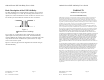
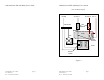
Outback Power PSX-240-Relay User’s Guide Outback Power PSX-240-Relay User’s Guide PSX-240-Relay Diagram AC Hot L1 Neutral Neutral Bus AC Hot L2 Aux +/- 25A Breakers Relay Fan Relay Contacts X-240 Thermal Switch Figure 2 PSX-240-Relay User’s Guide P/N: 900-0053-1 Rev. A – Released 12/19/2005 Page 12 PSX-240-Relay User’s Guide P/N: 900-0053-1 Rev.
Outback Power PSX-240-Relay User’s Guide ¨ Configuration The PSX-240-Relay must be connected to the AC output circuit of the FX system and is intended for installations that include the following: • An installation with two or more OutBack FX Series Inverter/Chargers wired to produce split phase 120/240 VAC. • The FX system is programmed using “OutBack” Stacking (not “Classic” Stacking).
Outback Power PSX-240-Relay User’s Guide • • If you don’t hear a click, press until the screen reads “OFF” and then until the screen reads “ON” and listen again for the click. If a click is heard, press until the screen shows “AUTO” mode. If still no click is heard, repeat all programming instructions. Contact your dealer if the programming is unsuccessful.
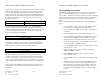
Outback Power PSX-240-Relay User’s Guide Outback Power PSX-240-Relay User’s Guide It is necessary to connect an AC neutral wire to the “AC Neutral” bus bar within the PSX-240-Relay. The torque for the screws in the neutral bus bar varies depending on the hole in which the wiring is installed. The larger of the two hole sizes in the neutral bar are the MAIN HOLES; the smaller holes are the TAP HOLES. The wire size range and torque specs are shown in the table below.