
Installation Manual Owner manual

65
WARN(ING) Screens
• acinfreqtoohigh:ACsourceisabove62Hz(upperlimit)andwillbedroppediffrequencygetsmuchhigher
• acinfreqtoolow:ACsourceisunder58Hz(lowerlimit)andwillbedroppediffrequencygetsmuchlower
• acinvoltagetoohigh:ACsource’svoltageisover140VAC(defaultlimit)andriskslossofFXconnection
• acinvoltagetoolow:ACsource’svoltageisunder114VAC(defaultlimit)andriskslossofFXconnection
• acininputcurrentexceedsmax:ACloadsaredrawingmorecurrentthantheratingoftheFXallows
• temperaturesensorfault:aninternalFXtemperaturesensorismalfunctioning
• internalcomm.errordetected:thereisacommunicationproblembetweentheMATEandtheFX
• internalfanfailuredetected:theFX’sinternalcoolingfanisnotoperatingproperly
• airtemp:displaysanumericvaluerepresentingtheairtemperaturearoundtheFX*
• fettemp:displaysanumericvaluerepresentingthetemperatureoftheFETs(FieldEectTransistors)*
• captemp:displaysanumericvaluerepresentingthetemperatureoftheripplecapacitors*
*Thesevaluesareusedfortroubleshootingpurposes.Thehigherthenumericalvalue,thecoolerthetemperature.
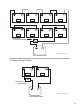
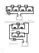
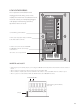
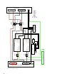
RTS, MATE/HUB WIRING
•RJ-11modularjackconnectsRTS,theoptional
externalbatterytemperaturesensor.*
•RJ-45jackconnectsMATEorHUBtoFXusingCAT5
cable.**
*WhenaHUBisused,plugtheRTSintotheMaster
FX, which should be plugged into HUB’s Port 01.
The RTS cable is folded and routed under the AC
Wiring Compartment’s Lexan cover, tting into a
small indentation in the aluminum casting between
the battery terminals. ONLY USE THE OUTBACK RTS;
OTHER BRANDS YIELD INCORRECT READINGS.
**IfthesystemhasmultipleFXsand/orOutBack
Charge Controllers, a HUB is required.
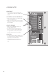
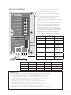
Status Lights
Battery Lights
GREEN
YELLOW
RED
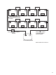
RJ-11 modular jack connects the RTS, the
external battery temperature sensor.
RJ-45 jack is used for external communications.
LED Color LED Action LED indicates
GREEN GREEN Inverter ON
Flashing GREEN Search mode or
Slave power
O Inverter OFF
YELLOW Solid YELLOW AC source is
connected
Flashing
YELLOW
AC input live,
waiting to con-
nect to OBX-IC
O No AC input
present
RED Solid RED
Critical error,
contact OutBack
Power Systems
Flashing RED Warning, a non-
critical error has
occurred
LED Color 12 VDC 24 VDC
48 VDC
GREEN (FULL) 12.5 or higher 25.0 or higher
50.0 or higher
YELLOW (OK) 11.5 to 12.5 23.0 to 25.0
46.0-49.6
RED (LOW) 11.5 or lower 23.0 or lower
46.0 or lower