
Installation Manual Owner manual

55
AC
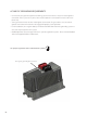
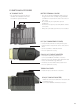
Follow these steps to wire the FX to your system:
1. Shut all AC breakers o or remove any fuses before connecting any wiring.
2. Shut o all DC breakers, including the PV breakers.
3. With all power o, run lengths of 6 AWG (13.3 mm
2
)
wire between the AC Wiring Compartment
Board AC out terminals and sucient over current protection via an AC circuit breaker whose
ampacity matches or exceeds the maximum AC input current of the FX model used in the system
(see FX product specications). The breaker should be installed inside of a metal chassis such as
OutBack’s FLEXware series or an existing panel.
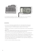
4. With the over current protection connected, run lengths of 6 AWG (13.3 mm
2
) wire between the
AC Wiring Compartment Board AC IN terminals and the AC input breaker. The breaker should be
installed inside of a metal chassis such as OutBack’s FLEXware series or an existing panel. The AC
input hot conductor must be supplied through an AC branch-rated circuit breaker whose ampacity
matches or exceeds the maximum AC input current of the FX model used in the system (see FX
product specications)
WARNING: FIRE HAZARD. While 60 amp over-current protection reduces the risk
of re, for further reduction, do not connect a single FX to both hot legs of a 120-240
VAC AC load center having multi-wire (common neutral) branch circuits connected.
Use either two FX Series Inverter/Chargers wired in a series conguration or an FW-
X240 Auto Transformer.
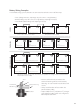
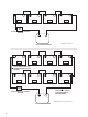
WIRE CONNECTIONS
NOTE: A system’s individual voltage requirements (120 VAC single phase, 120/240 VAC split phase, or
3-phase) as well as how each FX is to function all determine how the FXs are wired. Each FX must be
wired to the logical leg or phase of the system. Each FX must be programmed or “stacked” according
to this phase. Please see the FX and VFX Series Inverter/Charger Programming Manual before connecting
any wires to or from the FX.