Manual de instalación de los INVERSORES/ CARGADORES GTFX y GVFX SERIE LA interactivos con la red
Sobre OutBack Power Systems OutBack Power Systems es líder en tecnología de conversión de energía de avanzada. Nuestros productos incluyen inversores/cargadores de onda sinusoidal pura, controladores de punto de carga de energía máxima, componentes de comunicación entre sistemas, así como paneles de interruptores, interruptores, accesorios y sistemas montados. Información de contacto Teléfono: (+1) 360.435.6030 (América del Norte) (+34) 93.654.
TABLA DE CONTENIDOS Bienvenido al sistema inversor/cargador GTFX y GVFX SERIE LA de OutBack Power Systems..................................2 Modelos de los inversores/cargadores GTFX y GVFX SERIE LA......................................................................................................2 Piezas incluidas..................................................................................................................................................................................................
Bienvenido al sistema de inversores/cargadores GTFX y GVFX SERIE LA interactivos con la red de OutBack Power Los inversores/cargadores serie GTFX y GVFX (también conocidos como serie FX) ofrecen un completo sistema de conversión de energía —CC a CA, carga de baterías y conmutador de transferencia de CA— que presta un completo servicio interactivo con la red. También pueden usarse en aplicaciones autónomas o de respaldo. Estos sistemas están diseñados para interiores o lugares cerrados.
INSTRUCCIONES IMPORTANTES DE SEGURIDAD ¡LÉALAS PRIMERO! GUARDE ESTAS INSTRUCCIONES Lea todas las instrucciones y señales de precaución del FX y las baterías, y todas las secciones pertinentes de este manual de instalación para el usuario y los manuales de otros componentes antes de usar el sistema. Tenga precaución al trabajar con corrientes eléctricas, componentes eléctricos y baterías.
ADVERTENCIA: RIESGO DE EXPLOSIÓN. TRABAJAR CERCA DE BATERÍAS DE PLOMOÁCIDO PUEDE SER PELIGROSO. LAS BATERÍAS GENERAN GASES EXPLOSIVOS DURANTE SU FUNCIONAMIENTO NORMAL. Diseñe el compartimiento de la batería para evitar la acumulación y la concentración de gas hidrógeno en los “espacios vacíos” de la parte superior del compartimiento. Ventile el compartimiento de la batería desde su punto más alto hacia el exterior.
PROTECCIÓN DEL SISTEMA Los sistemas eléctricos están diseñados para protegerlo y para proteger los cables, los componentes y los dispositivos conectados al sistema. Cada FX debe ser parte de un sistema eléctrico conectado a tierra en forma permanente (consulte la página 9). La conexión a tierra protege a las personas y al equipo contra las descargas eléctricas. Dicha conexión debe realizarse conforme a los códigos eléctricos locales y nacionales.
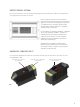
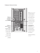
ORIGEN DEL CABLEADO DE CA Una tapa Lexan protege la placa del compartimiento de cableado de CA. Placa de cableado de CA PLACA DEL COMPARTIMIENTO DE CABLEADO DE CA • Bloque de terminales de CA: asegura las conexiones de CA al FX con tornillos prisioneros ���������� • AC HOT OUT (SALIDA CON CORRIENTE ALTERNA): suministra energía a las cargas. �������������� • AC NEUTRAL OUT (SALIDA DEL NEUTRO DE CA): actúa como la rama neutra para las cargas que suministra el FX.
TERMINALES DE BAJO VOLTAJE ���������� Nota: Mantenga apretados los tornillos del bloque de terminales del cableado de control y el bloque en sí mismo asegurado con firmeza a la placa de CA. De lo contrario, es posible que el FX no funcione correctamente. El bloque de terminales se puede desenchufar para facilitar la instalación de los cables y la desinstalación/ reinstalación del FX.
REQUISITOS PARA LA CONEXIÓN A TIERRA DE CA Y CC • El FX sólo debe conectarse a un sistema de cableado permanente con conexión a tierra. Asegúrese de que el sistema sólo tenga una conexión de tierra-neutro en todo momento. Algunos códigos exigen que esta conexión se realice en el panel principal solamente. • Algunos generadores tienen su propia conexión de tierra-neutro. Si se usa un generador, será necesario desconectar la conexión de tierra-neutro para el sistema funcione correctamente.
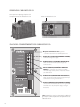
PIEZAS Y ACCESORIOS DEL FX PLACA DEL CONDUCTO DE CA • En el caso de las instalaciones que no usan un FW-ACA opcional, el conducto de CA se conecta con la placa del conducto de CA. TAPAS DE LOS TERMINALES DE LA BATERÍA • Los tapones son de plástico duro y tienen un diseño de cierre a presión. Quítelos con cuidado; para ello, inserte un destornillador de punta plana en las ranuras de los laterales de cada tapa. • En el caso de las instalaciones expuestas, tal vez se necesite un conducto de CC.
20,955 cm (8,25”) 32,03 cm (13”) 41,275 cm (16,25”) • Inserte los sujetadores adecuados en las cuatro esquinas del FX para asegurar la instalación. • El peso varía entre 56 y 62,6 libras (25,40 kg y 28,395 kg), según el modelo. MONTAJE • El inversor/cargador serie FX está aprobado para montarse solamente en interiores o lugares cerrados protegidos. • El FX debe asegurarse a una superficie de montaje firme capaz de soportar su peso mediante los sujetadores adecuados.
CONEXIONES DE LOS CABLES Nota: Los requisitos individuales de voltaje de un sistema (monofásico de 120 V CA, de fase dividida de 120/240 V CA o trifásico), así como el funcionamiento de cada FX, determinan el cableado de los FX. Cada FX debe cablearse a la fase o la rama lógica del sistema, y debe programarse o “apilarse” conforme a esta fase. Consulte el Manual de programación de los inversores/cargadores serie FX y VFX antes de conectar cualquier cable hacia o desde el FX.
CC • Para conectar los cables de la batería a los terminales de CC, use lengüetas engarzadas y selladas de terminal en anillo de cobre con orificios de 5/16” (0,79 cm) o lengüetas de tipo compresión. También se pueden usar lengüetas de cable soldadas. • Use los tamaños de cable recomendados (consulte la página 36) para reducir las pérdidas y garantizar el alto rendimiento del FX (los cables más pequeños pueden disminuir el rendimiento y dañar la unidad).
EJEMPLOS DE CABLEADO DE LAS BATERÍAS En los sistemas de energía renovable, las baterías se pueden conectar entre sí en una de tres maneras: EN SERIE • En serie (el voltaje aumenta; el amperaje permanece igual como una sola batería) • En paralelo (el voltaje permanece igual como una sola batería; el amperaje aumenta) • En serie/paralelo (el voltaje y el amperaje aumentan) - 12 V/200 amperios/hora 12 V/200 amperios/hora EN PARALELO 12 V + 12 V + 12 V + 12 V = 48 V 12 V/200 amperios/hora 12 V/200 ampe
- 6 VOLTIOS - - 6 VOLTIOS 6 VOLTIOS 6 VOLTIOS DISPOSITIVO DE DESCONEXIÓN DE CC (FUSIBLE O INTERRUPTOR DE CIRCUITO) - EN SERIE, FX DE 24 VOLTIOS INVERSOR/CARGADOR DE 24 VOLTIOS - 6 VOLTIOS 6 VOLTIOS LA CADENA 1 EN SERIE SE CONECTA CON EL TERMINAL POSITIVO DEL INVERSOR/CARGADOR 6 VOLTIOS 6 VOLTIOS CADENA 1 EN SERIE - 6 VOLTIOS - - - - 6 VOLTIOS 6 VOLTIOS 6 VOLTIOS CADENA 2 EN SERIE DISPOSITIVO DE DESCONEXIÓN DE CC (FUSIBLE O INTERRUPTOR DE CIRCUITO) - LA CADENA 2 EN SERIE SE CONE
- 6 VOLTIOS 6 VOLTIOS 6 VOLTIOS - 6 VOLTIOS - 6 VOLTIOS - - 6 VOLTIOS 6 VOLTIOS 6 VOLTIOS DISPOSITIVO DE DESCONEXIÓN DE CC (FUSIBLE O INTERRUPTOR DE CIRCUITO) EN SERIE, FX DE 48 VOLTIOS INVERSOR/CARGADOR DE 48 VOLTIOS Ejemplos de cableado de baterías de 12 V 6 VOLTIOS 6 VOLTIOS 6 VOLTIOS - - 12 VOLTIOS 6 VOLTIOS 12 VOLTIOS DISPOSITIVO DE DESCONEXIÓN DE CC (FUSIBLE O INTERRUPTOR DE CIRCUITO) EN SERIE, FX DE 24 VOLTIOS INVERSOR/CARGADOR DE 24 VOLTIOS 15
- 12 VOLTIOS - - 12 VOLTIOS 12 VOLTIOS 12 VOLTIOS DISPOSITIVO DE DESCONEXIÓN DE CC (FUSIBLE O INTERRUPTOR DE CIRCUITO) - EN SERIE, FX DE 48 VOLTIOS INVERSOR/CARGADOR DE 48 VOLTIOS - 12 VOLTIOS 12 VOLTIOS LA CADENA 1 EN SERIE SE CONECTA CON EL TERMINAL POSITIVO DEL INVERSOR/CARGADOR CADENA 1 EN SERIE - 12 VOLTIOS 12 VOLTIOS CADENA 2 EN SERIE DISPOSITIVO DE DESCONEXIÓN DE CC (FUSIBLE O INTERRUPTOR DE CIRCUITO) EN SERIE/PARALELO, FX DE 24 VOLTIOS INVERSOR/CARGADOR DE 24 VOLTIOS 16
- 12 VOLTIOS 12 VOLTIOS LA CADENA 1 EN SERIE SE CONECTA CON EL TERMINAL POSITIVO DEL INVERSOR/CARGADOR 12 VOLTIOS 12 VOLTIOS CADENA 1 EN SERIE - 12 VOLTIOS - - - - 12 VOLTIOS 12 VOLTIOS 12 VOLTIOS CADENA 2 EN SERIE DISPOSITIVO DE DESCONEXIÓN DE CC (FUSIBLE O INTERRUPTOR DE CIRCUITO) - INVERSOR/CARGADOR DE 48 VOLTIOS LA CADENA 2 EN SERIE SE CONECTA CON EL TERMINAL NEGATIVO DEL INVERSOR/CARGADOR EN SERIE/PARALELO, FX DE 48 VOLTIOS 17
NOTAS SOBRE EL CABLEADO DE CA AC HOT OUT • El calibre del conductor con corriente alterna de salida (negro) debe adecuarse a los interruptores y las cargas.
CABLEADO DE BAJO VOLTAJE Este bloque de terminales de seis posiciones se puede desenchufar para facilitar el cableado y simplificar la extracción y la reinstalación de un FX. Para que el FX funcione correctamente, el bloque de terminales debe estar bien enchufado y asegurado. De lo contrario, pueden ocurrir errores funcionales.
Antes de instalar un conmutador de encendido/apagado, si la salida de CA del FX está apagada, verifique que el puente conector esté presente y bien conectado. Debe corroborar que el sistema esté funcionando correctamente. Si posteriormente decide instalar un MATE de OutBack, tenga presente que el conmutador instalado anula el control que proporciona el MATE si el conmutador está configurado en la posición de apagado.
CABLEADO DE MATE/HUB, RTS El enchufe hembra RJ-45 se usa para las comunicaciones externas. • El enchufe hembra modular RJ-11 conecta el RTS, el sensor de temperatura externo opcional de la batería.* • El enchufe hembra RJ-45 conecta el MATE o HUB al FX con el cable CAT 5.** ���������� �������������� *Cuando use un HUB, enchufe el RTS en el FX maestro, que a su vez debe enchufarse en el puerto 01 del HUB.
TIPOS DE INSTALACIÓN SISTEMA FX SIMPLE • El tamaño de todo el cableado de CA del FX debe ser apto para operar con CA de 60 amperios o más. • Para los modelos FX se debe usar un interruptor de 60A • Un FX simple puede alimentar en forma ininterrumpida de 2 kW a 3,6 kW de cargas, según el modelo que se use. • La salida de un FX simple se puede aumentar a 240 V CA con un transformador FX-X240.
CONFIGURACIÓN EN SERIE DE FX DOBLE • Este sistema puede alimentar en forma ininterrumpida entre 4 kW y 7,2 kW de cargas de 120/240 V CA, según el modelo que se use. • Conectar más potencia que la capacidad nominal continua del FX puede causar el disparo de los interruptores o la interrupción de la salida de CA del FX. • El tamaño de todo el cableado de CA del FX debe ser apto para operar con CA de 60 amperios o más.
AC INPUT L2 RED TBB Apilamiento en serie con dos FX 24 AC INPUT L1 BLACK TBB AC INPUT FROM UTILITY GRID OR AC SOURCE BLACK HUB CHASSIS GROUND AC HOT IN 1ST MATE AC HOT OUT HUB/MATE DISPLAY AC NEUTRAL OUT AC NEUTRAL IN AC HOT OUT HUB/MATE AC NEUTRAL OUT AC NEUTRAL IN L1 MASTER CHASSIS GROUND AC HOT IN 10 9 8 7 6 5 4 3 2 1 GREEN CAT 5 COMM CABLES 60 AMP INPUT BREAKER GREEN RED L2 SLAVE WHITE WHITE BLACK BLACK RED MECHANICAL INTERLOCK 60 AMP OUTPUT BREAKERS AC INPUT AND AC OU
SISTEMA FX TRIFÁSICO • Este sistema produce 120 V CA por fase y 208 V CA de fase a fase. Sólo puede haber un FX por fase en un sistema trifásico. • El tamaño de todo el cableado de CA del FX debe ser apto para operar con CA de 60 amperios o más. • Este sistema puede alimentar en forma ininterrumpida hasta 10,8 kW de cargas, según el modelo que se use.
Sistema trifásico 26
ARRANQUE AUTOMÁTICO DEL GENERADOR En el siguiente esquema, se muestra cómo conectar un relé que se interconecta con el generador bifilar de arranque. Los generadores trifilares de arranque necesitan un adaptador, como el Atkinson GSCM, disponible en www.atkinsonelectronics.com. TWO WIRE START GENERATOR HOOK UP GENERATOR NO NC COM COIL 12V RELAY INVERTER ON/OFF AUX + AUX XCT XCT + La mayoría de los relés de 12 V servirán para arrancar el generador.
FUENTES DE CA MÚLTIPLES CON EL INVERSOR FX Cuando un sistema tiene la opción de usar un generador o la red de distribución de energía eléctrica como su entrada de CA: • La línea de CA “con corriente” y la línea de CA “neutra” deben estar conectadas a la fuente apropiada. • Se puede realizar una conexión con un conmutador unipolar bidireccional (se puede obtener de los proveedores de componentes eléctricos), que tiene una conexión para cada cable de CA con corriente.
LISTA DE VERIFICACIÓN PARA LA INSTALACIÓN ÍTEM Sí NO ¿Se leyeron y revisaron todos los manuales? FX Controlador de carga de OutBack MATE HUB ¿Se montó el sistema con la cantidad de sujetadores del tamaño recomendado? ¿Se instaló el sistema conforme a los códigos locales? ¿Se realizó la inspección del sistema? ¿Se realizó la conexión a tierra permanente del sistema? ¿Usó el instalador el tipo y el calibre de cable recomendados por OutBack para el intervalo y la duración de la temperatura? ¿Todo el cablead
ESPECIFICACIONES GTFX2524LA Intervalo de voltaje de entrada de CC nominal 24 V CC Voltaje de CA de salida/Frecuencia 127 V CA/60 Hz Potencia nominal continua a 25 °C de temp.
GVFX3524LA Intervalo de voltaje de entrada de CC nominal 24 V CC Voltaje de CA de salida/Frecuencia 127 V CA/60 Hz Potencia nominal continua a 25 °C de temp.
INTERVALOS DE FRECUENCIAS, CORRIENTE Y VOLTAJE VOLTAJE DE SALIDA DE CA ESPECÍFICO DE UN SISTEMA SERIE LA INTERACTIVO CON LA RED 127 V CA a 60 Hz Monofásico Apilado en serie 127 V CA a 60 Hz por rama de salida de CA/254 V CA a 60 Hz entre las ramas de salida de CA Apilamiento trifásico 127 V CA a 60 Hz por rama de salida de CA (límite tres)/220 V CA a 60 Hz entre las ramas de salida de CA INTERVALO DE VOLTAJE DE CC DEL FX RECOMENDADO Nota: Los últimos dos dígitos del número de modelo indican el v
CORRIENTE DE ENTRADA DE CA MÁXIMA Una fuente de entrada de CA conectada al FX suministra potencia para dos circuitos de CA internos individuales: el conmutador de transferencia de CA y el sistema de carga de la batería. El conmutador de transferencia de CA transfiere la potencia de entrada de CA a las cargas de CA. El cargador de la batería del FX “retrocederá” si las cargas de CA totales —incluido el cargador— superan el límite de corriente de entrada de CA (la configuración predeterminada es 50 A CA).
POTENCIA DE SALIDA CONTINUA MÁXIMA El número de modelo de un inversor/cargador serie FX con los últimos dos dígitos cambiados a cero indica la potencia de salida continua máxima de la unidad. Por ejemplo, el modelo GTFX2524LA tiene una potencia de salida continua máxima de 2500 VA (voltio-amperios).
PREDETERMINADO MÍNIMO MÁXIMO Voltaje de mantenimiento 13,6 V CC 12 V CC 15 V CC Voltaje de absorción 14,4 V CC 13 V CC 16 V CC Voltaje de carga y ecualización 14,6 V CC 14 V CC 17 V CC Voltaje de mantenimiento repetido 12,5 V CC 12 V CC 13 V CC LBCO 10,5 V CC 9 V CC 12 V CC LBCI 12,5 V CC 10 V CC 14 V CC Venta de energía renovable 13 V CC 10 V CC 15 V CC Punto de ajuste de apagado 14 V CC 12 V CC 18 V CC Punto de ajuste de encendido 11 V CC 10 V CC 14 V CC Punto de ajus
TAMAÑOS DE CABLES El siguiente cuadro contiene información sobre los tamaños de cables, la resistencia de CC de los cables, y las áreas y los diámetros correspondientes de estos cables. Dicha información se puede usar para calcular la caída de voltaje de los cables o para encontrar un tamaño de cable equivalente. TAMAÑO (AWG) CC ÁREA DE SECCIÓN TRANSVERSAL Resistencia en omhios (1.
TAMAÑOS DE CABLE RECOMENDADOS POR LONGITUD Modelo de FX Amperaje de CC típico Amperaje según NEC 130 Trayecto de 1’ a 3’ (30,5 cm a 91,4 cm) 2/0 Trayecto de 3’ a 5’ (91,4 cm a 152,4 cm) 2/0 Trayecto de 5’ a 10’ (152,4 cm a 304 cm) 2/0 GTFX2524LA 104 GTFX3048LA GVFX3524LA GVFX3648LA 63 146 75 78 182 94 1/0 4/0 1/0 1/0 4/0 1/0 1/0 4/0 1/0 MANTENIMIENTO Si presenta algún daño o un mal funcionamiento, el FX debe ser reparado; su reparación debe estar a cargo de un usuario, instalador o centro de m
INFORMACIÓN SOBRE LA GARANTÍA LIMITADA POR DOS AÑOS Inversores/cargadores serie FX OutBack Power Systems, Inc. (“OutBack”) proporciona una garantía limitada por dos (2) años (“Garantía”) contra defectos en los materiales y la mano de obra para los inversores/cargadores serie FX/VFX (“Productos”) que se instalen en aplicaciones de ubicación fija.
Para solicitar mantenimiento en garantía, debe comunicarse con el servicio técnico de OutBack al (360) 435-6030 o a support@outbackpower.com dentro del período de vigencia de la garantía. El servicio técnico de OutBack intentará localizar la falla para validar si está relacionada con el Producto. Si se debe realizar mantenimiento en garantía, OutBack emitirá un número de Autorización de devolución de material (RMA).
Registro de la garantía limitada Complete este formulario para solicitar una Garantía limitada y envíelo a la siguiente dirección: OutBack Power Systems Inc. 19009 62nd Ave. NE Arlington, WA 98223 NOTA: Envíe una copia (no el original) de la factura de compra del Producto, para confirmar la fecha y el lugar de compra, el precio abonado y el modelo y número de serie del Producto.
41
Oficina corporativa 19009 62nd Avenue NE Arlington, WA USA (+1) 360-435-6030 www.outbackpower.com 42 Oficina de Ventas en Europa C/ Castelló, 17 08830 - Sant Boi de Llobregat BARCELONA, España +34.93.654.
GTFX and GVFX LA SERIES Grid-Interactive INVERTER/CHARGER Installation Manual 43
About OutBack Power Systems OutBack Power Systems is a leader in advanced energy conversion technology. Our products include true sine wave inverter/chargers, maximum power point charge controllers, system communication components, as well as breaker panels, breakers, accessories, and assembled systems. Contact Information Telephone: (+1) 360.435.6030 (North America) (+34) 93.654.
TABLE OF CONTENTS Welcome to the OutBack Power Systems GTFX and GVFX LA Series Inverter/Charger System............................46 GTFX and GVFX LA Series Inverter/Charger Models..........................................................................................................................46 Parts Included.................................................................................................................................................................................................
Welcome to the OutBack Power GTFX and GVFX LA Series Grid-Interactive Inverter/Charger System The GTFX and GVFX series Inverter/Chargers (also referred to as the FX series) offer a complete power conversion system—DC to AC, battery charging, and an AC transfer switch—which provide complete grid-interactive service. They can also be used in a stand-alone or back-up application. These systems are designed for indoor or enclosed locations.
R EA D F IR ST ! IMPORTANT SAFETY INSTRUCTIONS READ FIRST! SAVE THESE INSTRUCTIONS Read all instructions and cautionary markings on the FX, the batteries and all appropriate sections of this installation and user manual as well as other component manuals before using the system. Be cautious around electricity, electrical components, and batteries. Shocks, burns, injury, and even death can occur if an installer comes in contact with electricity.
WARNING: EXPLOSION HAZARD. WORKING NEAR LEAD ACID BATTERIES CAN BE DANGEROUS. BATTERIES GENERATE EXPLOSIVE GASES DURING NORMAL OPERATION. Design the battery enclosure to prevent accumulation and concentration of hydrogen gas in “pockets” at the top of the enclosure. Vent the battery compartment from the highest point to the outside. A sloped lid can also be used to direct the flow of hydrogen to the vent opening.
SYSTEM PROTECTION Electrical systems are designed to protect you, the wires, the components, and the devices served by the system. Each FX must be part of a permanently grounded electrical system (see page 9). Grounding protects people and equipment from electrical shock. Grounding must be done according to local and national electrical codes. OutBack circuit breakers—rated at 100% duty cycle— protect wiring by limiting the amount of current entering a system.
AC WIRING ORIGINATION Lexan cover protects AC Wiring Compartment Board AC Wiring Board AC WIRING COMPARTMENT BOARD AC Terminal Block--secures AC connections to the FX using set screws ���������� • AC HOT OUT supplies power to the loads. �������������� • AC NEUTRAL OUT acts as neutral leg for loads supplied by the FX. ����������������� • CHASSIS GROUND connections are common and act as grounds for both the incoming and outgoing AC circuits.
LOW VOLTAGE TERMINALS ���������� �������������� Note: Keep Control Wiring Terminal Block screws tight and the block itself secured tightly to AC Board. Otherwise, the FX can malfunction. The Terminal Block can be unplugged for easier wire installation and removal/ reinstallation of the FX.
AC AND DC GROUNDING REQUIREMENTS • Connect only to a grounded, permanent wiring system. Ensure there is only one neutral-ground connection in the system at any time. Some codes require this connection be made at the main panel only. • Some generators have their own neutral-ground connection. If a generator is used, its neutralground connection will need to be disengaged for proper system operation.
FX PARTS AND ACCESSORIES AC CONDUIT PLATE • AC conduit connects to the AC Conduit Plate for installations which do not utilize an optional FW-ACA. BATTERY TERMINAL COVERS • The caps are made of stiff plastic with a snap-on design; remove them carefully using a flat-blade screwdriver inserted into the slots on the sides of each cover. • DC conduit may be required for exposed installations. • The DCA cover option (see below) allows conduit connection. • Always keep the battery terminal covers installed.
20.955 cm (8.25””) 32.03 cm (13”) 41.275 cm (16.25”) • Insert appropriate fasteners at all four corners of the FX for a secure installation. • Weight varies from 56-62.6 pounds (25.40 - 28.395 kg) depending on the model MOUNTING • The FX Series Inverter/Charger is approved for indoor or enclosed protected mounting only. • An FX must be secured with appropriate fasteners to a sturdy mounting surface capable of supporting its weight. It is easier for two people to install the FX due to its weight.
WIRE CONNECTIONS Note: A system’s individual voltage requirements (120 VAC single phase, 120/240 VAC split phase, or 3-phase) as well as how each FX is to function all determine how the FXs are wired. Each FX must be wired to the logical leg or phase of the system. Each FX must be programmed or “stacked” according to this phase. Please see the FX and VFX Series Inverter/Charger Programming Manual before connecting any wires to or from the FX. AC Follow these steps to wire the FX to your system: 1.
DC • Use crimped and sealed copper ring terminal lugs with 5/16” (0.79 cm) hole or compression-type lug to connect battery cables to DC terminals. Soldered cable lugs are also acceptable. • Use recommended cable sizes (see page 36) to reduce losses and ensure high performance of FX (smaller cables can reduce performance and possibly damage the unit). • Keep cables together (e.g., using a tie-wrap) as much as possible.
Battery Wiring Examples In renewable energy systems, batteries are connected to each other in one of three ways: SERIES • Series (voltage increases, amperage stays the same as a single battery) • Parallel (voltage stays the same as a single battery, amperage increases) • Series/Parallel (both voltage and amperage increase) - 12V/200 Amp-Hours 12V/200 Amp-Hours PARALLEL 12 V + 12 V + 12 V + 12 V = 48 V - Voltage remains at 12V SERIES/PARALLEL 12V/200 Amp-Hours - 12V/200 Amp-Hours 12 V 200 Amp-H
- 6 VOLT - - 6 VOLT 6 VOLT 6 VOLT DC DISCONNECT (FUSE OR CIRCUIT BREAKER) - SERIES/24 VOLT FX 24 VOLT INVERTER/CHARGER - 6 VOLT 6 VOLT 6 VOLT 6 VOLT SERIES STRING 1 SERIES STRING 1 CONNECTS TO INVERTER/CHARGER’S POSITIVE TERMINAL - 6 VOLT - - - - 6 VOLT 6 VOLT 6 VOLT SERIES STRING 2 DC DISCONNECT (FUSE OR CIRCUIT BREAKER) - SERIES STRING 2 CONNECTS TO INVERTER/CHARGER’S NEGATIVE TERMINAL SERIES/PARALLEL/24 VOLT FX 24 VOLT INVERTER/CHARGER 58
- 6 VOLT 6 VOLT 6 VOLT - - 6 VOLT - - 6 VOLT 6 VOLT - - 6VOLT 6 VOLT DC DISCONNECT (FUSE OR CIRCUIT BREAKER) SERIES/48 VOLT FX 48 VOLT INVERTER/CHARGER 12V Battery Wiring Examples - 12 VOLT 12 VOLT DC DISCONNECT (FUSE OR CIRCUIT BREAKER) SERIES/24 VOLT FX 24 VOLT INVERTER/CHARGER 59
- 12 VOLT 12 VOLT - 12VOLT 12 VOLT DC DISCONNECT (FUSE OR CIRCUIT BREAKER) - SERIES/48 VOLT FX 48 VOLT INVERTER/CHARGER - 12 VOLT 12 VOLT SERIES STRING 1 CONNECTS TO INVERTER/CHARGER’S POSITIVE TERMINAL SERIES STRING 1 - 12 VOLT 12 VOLT SERIES STRING 2 DC DISCONNECT (FUSE OR CIRCUIT BREAKER) SERIES/PARALLEL/24 VOLT FX 24 VOLT INVERTER/CHARGER 60
- 12 VOLT 12 VOLT 12 VOLT 12 VOLT SERIES STRING 1 SERIES STRING 1 CONNECTS TO INVERTER/CHARGER’S POSITIVE TERMINAL - 12 VOLT - - - - 12 VOLT 12 VOLT 12 VOLT SERIES STRING 2 DC DISCONNECT (FUSE OR CIRCUIT BREAKER) - SERIES STRING 2 CONNECTS TO INVERTER/CHARGER’S NEGATIVE TERMINAL 48 VOLT INVERTER/CHARGER SERIES/PARALLEL/48 VOLT FX 61
AC WIRING NOTES AC HOT OUT • AC hot output conductor (black) wire gauge must be sized to the breakers and loads. ���������� AC NEUTRAL OUT/AC NEUTRAL IN �������������� ����������������� ����������������� CHASSIS GROUND 62 ���� ���� ���� ���� ������ �������� ����� ����� ������ �������� ��� ������������ �������� �� • The AC hot input conductor (black) must be supplied through a 60 amp maximum AC branch rated circuit breaker. • 6 AWG (0.184” or 4.
LOW-VOLTAGE WIRING This six-position terminal block can be unplugged to make wiring easier and to simplify the removal and reinstallation of an FX. It must be securely and completely plugged in for proper FX functioning. Otherwise, operational errors can occur.
Prior to installing an ON/OFF switch, if the FX’s AC output is off, check that the jumper is present and well-connected before installing a switch. You want to confirm the system is in good working order. Should you decide to install an OutBack MATE at a later date, bear in mind the installed switch overrides the control provided by the MATE if the switch is set to OFF. If the switch is set to ON, the MATE will function normally and control the inverter(s).
RTS, MATE/HUB WIRING RJ-11 modular jack connects the RTS, the external battery temperature sensor. RJ-45 jack is used for external communications. • RJ-11 modular jack connects RTS, the optional external battery temperature sensor.* • RJ-45 jack connects MATE or HUB to FX using CAT5 cable.** ���������� �������������� *When a HUB is used, plug the RTS into the Master FX, which should be plugged into HUB’s Port 01.
INSTALLATION TYPES SINGLE FX SYSTEM • • • • All FX AC wiring must be sized to handle 60 amps AC or more. A 60A input breaker must be used for all FX models. A single FX can continuously power 2.0 kW to 3.6 kW of loads depending on which model is used. The output of a single FX can be stepped up to 240 VAC with the FX-X240 transformer.
SERIES DUAL FX CONFIGURATION • This system can continuously power between 4.0 kW and 7.2 kW of 120/240 VAC loads, depending on which model is used. • Connecting more power than the continuous rating of the FX may cause breakers to trip or the FX to shut off its AC output. • All FX AC wiring must be sized to handle 60 amps AC or more. Note: • Stacking FXs in series means there are FXs directly connected to two legs of a 120/240 VAC input source, and to two separate 120 VAC output legs.
AC INPUT L2 RED TBB Series Stacking Using Two FXs 68 AC INPUT L1 BLACK TBB AC INPUT FROM UTILITY GRID OR AC SOURCE BLACK HUB CHASSIS GROUND AC HOT IN 1ST MATE AC HOT OUT HUB/MATE DISPLAY AC NEUTRAL OUT AC NEUTRAL IN AC HOT OUT HUB/MATE AC NEUTRAL OUT AC NEUTRAL IN L1 MASTER CHASSIS GROUND AC HOT IN 10 9 8 7 6 5 4 3 2 1 GREEN CAT 5 COMM CABLES 60 AMP INPUT BREAKER GREEN RED L2 SLAVE WHITE WHITE BLACK BLACK RED MECHANICAL INTERLOCK 60 AMP OUTPUT BREAKERS AC INPUT AND AC OUTP
3-PHASE FX SYSTEM • This system produces 120 VAC per phase and 208 VAC from phase to phase. There can only be one FX per phase on a 3-phase system. • All FX AC wiring must be sized to handle 60 amps AC or more. • This system can power continuously up to 10.8 kW of loads depending on which model is used. • Connecting more power than the continuous rating of the FX may cause breakers to trip or the FX to shut off its AC output.
Three-Phase System 70
GENERATOR AUTO START The following schematic shows how to hook up a relay that interfaces with the two-wire start generator. Three-wire start generators require an adapter like the Atkinson GSCM available at www.atkinsonelectronics.com. TWO WIRE START GENERATOR HOOK UP GENERATOR NO NC COM COIL 12V RELAY INVERTER ON/OFF AUX + AUX XCT XCT + Most 12V relays will work for generator starting. Select one between 2 and 30 amp contacts.
MULTIPLE AC SOURCES WITH THE FX INVERTER When a system has the option of using either a generator or the utility grid as their AC input: • Both the AC “Hot” and AC “Neutral” lines must be connected to the appropriate source. • A connection can be made using a single-pole, double-throw switch (available from electrical component suppliers) which has one connection each for AC hot wire. • This switch must be rated to handle the system’s maximum AC voltage and AC current.
INSTALLATION CHECK LIST ITEM YES NO All manuals read and reviewed? FX OutBack Charge Controller MATE HUB System mounted with the recommended number and sized fasteners? System installed according to local codes? System inspected? System permanently grounded? Did the installer use OutBack recommended wire type and gauge adjusted for temperature ratings and length? All AC wiring rated for 75° C or higher? Battery cables rated 75° C or higher? 6 AWG (0.184” or 4.
SPECIFICATIONS GTFX2524LA Nominal DC Input Voltage Range 24 VDC Output AC Voltage / Frequency 127 VAC / 60 HZ Continuous Power Rating at 25°C Ambient 2500 VA Continuous AC RMS Output at 25°C 19.
GVFX3524LA Nominal DC Input Voltage Range 24 VDC Output AC Voltage / Frequency 127 VAC / 60 HZ Continuous Power Rating at 25°C Ambient 3500 VA Continuous AC RMS Output at 25°C 27.
VOLTAGE, CURRENT AND FREQENCY RANGES SPECIFIED AC OUTPUT VOLTAGE OF AN LA SERIES GRID-INTERACTIVE SYSTEM Single Phase 127 VAC at 60 Hz Series Stacked 127 VAC at 60 Hz per AC output leg / 254 VAC at 60 Hz between the AC output legs Three Phase Stacked 127 VAC at 60 Hz per AC output leg (limit three) / 220 VAC at 60 Hz between AC output legs RECOMMENDED FX DC VOLTAGE RANGE Note: The last two digits in the model number designate the nominal DC voltage. Example: GVFX3648LA =48V DC Voltage.
MAXIMUM AC INPUT CURRENT An AC input source connected to the FX supplies power for two separate internal AC circuits – the AC transfer switch and the battery charging system. The AC transfer switch transfers the AC input power to the AC loads. The FX’s battery charger will “back off” if the total AC loads—including the charger— exceed the AC input current limit (default setting is 50 AAC). This “Input Limit” can be adjusted using the MATE to avoid overloading a generator or trip a circuit breaker.
MAXIMUM CONTINUOUS OUTPUT POWER An FX Series Inverter/Charger’s model number indicates its maximum continuous output power by changing the last two digits to zeros. For instance, a GTFX2524LA has a maximum continuous output power of 2500VA (volt-amps). GTFX2524LA 2500 VA (VA = volt-Amps) GTFX3048LA 3000 VA GVFX3524LA 3500 VA GVFX3648LA 3600 VA MAXIMUM OVERCURRENT PROTECTION This rating specifies the proper overcurrent protection size. • • • • 78 OBB breakers are panel-mount circuit breakers.
12 VDC System DEFAULT MINIMUM MAXIMUM Float Voltage 13.6 VDC 12 VDC 15 VDC Absorb Voltage 14.4 VDC 13 VDC 16 VDC EQ Voltage 14.6 VDC 14 VDC 17 VDC ReFloat 12.5 VDC 12 VDC 13 VDC LBCO 10.5 VDC 9 VDC 12 VDC LBCI 12.5 VDC 10 VDC 14 VDC Sell RE 13 VDC 10 VDC 15 VDC Off Set Point 14 VDC 12 VDC 18 VDC On Set Point 11 VDC 10 VDC 14 VDC Load Shed Off Set Point 11 VDC 10 VDC 14 VDC Vent Fan ON Set Point 13 VDC 10 VDC 16 VDC Diversion ON Set Point 14.
WIRE SIZES The following chart contains information on wire sizes, the DC resistance of the wires and the corresponding diameters and areas of these wires. This information can be used to calculate the voltage drop of the wires or to find an equivalent wire size. SIZE DC CROSS-SECTIONAL AREA APPROXIMATE DIAMETER (with insulation) (AWG) Resistance in Ohms (1000 feet) 14 3.14 12 1.98 10 1.24 8 0.78 6 0.50 4 0.31 2 0.19 1 0.15 1/0 0.12 2/0 0.10 3/0 0.08 4/0 0.06 INCHES 0.
Recommended Wire Sizes by Length FX Model NEC AMPS 1-3’ one way 3-5’ one way 5-10’ one way GTFX2524LA Typical DC AMPS 104 130 2/0 2/0 2/0 GTFX3048LA GVFX3524LA GVFX3648LA 63 146 75 78 182 94 1/0 4/0 1/0 1/0 4/0 1/0 1/0 4/0 1/0 MAINTENANCE If damaged or malfunctioning, the FX should be repaired by a qualified user, installer, or service center following OutBack Power Systems’ instructions and guidelines. Please contact your energy dealer for assistance.
TWO YEAR LIMITED WARRANTY INFORMATION FX Series Inverter/Charger Products OutBack Power Systems, Inc. (“OutBack”) provides a two year (2) limited warranty (“Warranty”) against defects in materials and workmanship for its FX/VFX Series Inverter/Charger products (“Product(s)”) if installed in fixed location applications. The term of this Warranty begins on the Product(s) date of manufacture or the initial purchase date as indicated on the warranty registration card submitted to OutBack, whichever is greater.
To request warranty service, you must contact OutBack Technical Services at (360) 435-6030 or support@ outbackpower.com within the effective warranty period. OutBack Technical Support will attempt to troubleshoot the product and validate that the failure is product related. If warranty service is required, OutBack will issue a Return Material Authorization (RMA) number. A request for an RMA number requires all of the following information: 1.
Limited Warranty Registration Complete this form to request a Limited Warranty, and return it to: OutBack Power Systems Inc. 19009 62nd Ave. NE Arlington, WA 98223 NOTE: Please submit a copy (not the original) of the Product purchase invoice, which confirms the date and location of purchase, the price paid, and the Product Model and Serial Number.
85
Corporate Office 19009 62nd Avenue NE Arlington, WA USA (+1) 360-435-6030 www.outbackpower.com European Sales Office C/ Castelló, 17 08830 - Sant Boi de Llobregat BARCELONA, España +34.93.654.