
OutBack Power GSLC Installation Manual

Introduction
900-0123-01-00 Rev C 9
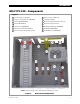
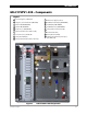
GSLC175-230 – Components
Figure 5 GSLC175-230 Components
Inverter Negative (–) DC Bus Bar
Negative (–) Terminal Bus Bar (TBB-WHITE)
Ground TBB (TBB-GROUND)
Neutral TBB (TBB-BLUE)
PV Positive (+) TBB (TBB-RED)
DC Positive (+) Cable Plate (FW-BBUS)
Main Inverter Disconnect(s) (PNL-175-DC)
Inverter Positive (+) DC Bus Bar
Shunt (FW-SHUNT500)
AC Input Circuit Breakers (PNL-50-AC-230V)
Maintenance Bypass Interlock
AC TBB (Inverter Output) (TBB-BROWN)
AC TBB (Grid) (TBB-BROWN)
AC TBB (Generator) (TBB-BROWN)
Legend
12
11
1
2
3
4
5
6
7
8
9
10
14
13
NOTE:
The factory wiring has been omitted from this illustration for clarity.