
Outback Power GS4048A and GS8048A Installation Manual

Installation
900-0160-01-00 Rev A 17
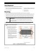
Terminals and Ports
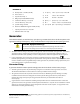
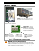
Figure 12 DC Terminals, Ribbon Cables, and Auxiliary Terminals
WARNING: Shock Hazard and Equipment Damage
It may be necessary to remove the ribbon cables in the course of servicing the Radian. (This is detailed in
the Radian service manual.) The cables must never be removed until all power has been disconnected from
the Radian for a minimum of one minute. If the cables are removed prematurely, the Radian’s capacitors
will retain a sizable charge, which can cause electrical shock or severe equipment damage during normal
handling. This damage is not covered under the unit’s warranty.
12V AUX: Delivers 12 Vdc up to
0.7
amps (8.4 watts). The output can
be switched on and off for many
functions. See page 26 for details.
SWITCH INV eceives wires for a
manual
on/off switch to control the
inverte
r. See page 25 for instructions.
NOTE:
The ON/OFF INV jumper (J3)
overrides these terminals when installed.
(See above.)
RELAY AUX: Relay contacts with no
voltage (
10 amps at 250 Vac or 30 Vdc).
The relay can be
switched on and off for
many functions. See page 26 for details.
ON/OFF INV JUMPER (J3): Overrides the
SWITCH INV terminals when installed. When
installed, the inverter is ON. The ON or OFF
states can then only be controlled by the MATE3.
NOTE: J3 is installed to the ON position during
manufacture, but the Radian inverter is given an
external OFF command at the same time. Its
initial state will be OFF.
DC TERMINALS Connects to the battery cables and DC system. There are
two DC
positive and two DC negative terminals. Each DC positive terminal
requires separate cables and separate overcurrent protection. See page
20
for instructions.
RIBBON CABLES Connects the Radian’s power
modules and control board. See Warning below.
The functions for each set of AUX contacts can be programmed
using the system di
splay.