
Outback Power GS4048A and GS8048A QuickStart Guide

Installation
900-0162-01-00 Rev A.vsd\Page-2\2014-01-24
©2014 OutBack Power Technologies. All Rights Reserved.
RADIAN Series
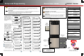
16" (40.6 cm)
Plywood (Optional)
Wall Board
Wall
Stud
Wall Bracket
Wall
Stud
4.1"
(10.4 cm)
5.0"
(12.7 cm)
6.0"
(15.2 cm)
8.0"
(20.3 cm)
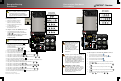
AC Circuit Breakers
1
GFDI
2
3
4
DC Terminals - Inverter
AC Terminals - Inverter
5
DC Circuit Breakers
6
PV Circuit Breakers
Charge Controller Terminals
7
8
Mechanical Interlock (Bypass)
9
10
Communication Ports
Auxiliary Terminals
11
12
13
14
15
AC OUT Bus Bar L1
16
17
18
19
AC OUT Bus Bar L2
GRID IN Bus Bar L1
GRID IN Bus Bar L2
GEN IN Bus Bar L1
GEN IN Bus Bar L2
AC Neutral
Ground
20
DC Positive (+) Plate (not used
on GSLC175PV1-120/240)
PV Negative (–) Terminals
21
22
PV Positive (+) Bus Bars
DC Negative (–) Plate (GS-SBUS)
N
E
U
L1 L2
GRID
L1 L2
GEN
N
E
U
N
E
U
L1 L2
OUT
RELAY
AUX
+ -
12V
AUX
Switch
INV
Remote
Battery
Temp
FM80 #1 FM80 #2
MATE3
HUB
10.3
GS8048A
GSLC175-PV-120/240
1
2 2
3
4
5
7
8
8
9
9
9
9
9
10
10
10
6
ON/OFF
INV
11
12
13
14
15
16
17
18
19
20
21
21
22
20
AC Wire Sizes and Torque Values
OutBack recommends that conductors be
#6 AWG THHN copper, or larger, rated to 75°C
(minimum) unless local code requires otherwise.
AWG In-lb
#14 to #10 20
#8 25
#6 to #4 35
#3 35
#2 40
#1 50
1/0 50
mm
2
2.5 to 6
10
16 to 25
35
35
50
70
Nm
2.3
2.8
4.0
4.0
4.5
5.6
5.6
Wire Size Torque
Torque Requirements
Plywood
(Optional)
Wall Board
Wall
Bracket
Wall Stud
N
E
U
L1 L2
GRID
L1 L2
GEN
N
E
U
N
E
U
L1 L2
OUT
RELAY
AUX
+ -
12V
AUX
Switch
INV
Remote
Batter y
Temp
ON/OFF
INV
28.0"
(71.1 cm)
16" (40.6 cm)
0.5" (1.3 cm)0.5" (1.3 cm)
29.1"
(74.0 cm)
45.0"
(114.3
cm)
13.7"
(34.8 cm)
Inverter
Bracket
8.75"
(22 cm)
Circuit Breaker
Stud
Torque
In-lb Nm
M8 20 2.3
¼ - 20 35 4.0
5/16 - 18 50 5.6
3/8 - 16 225 25.4
DC Plates
Torque
In-lb Nm
Upper holes (+)
Shunt Bolts (–)
and GS-SBUS
Lower holes (+)
60
6.8
5.6
6.8
60
50
60
Minimum DC Cable based on
the DC Circuit Breaker
Torque
In-lb Nm
50 5.6
225 25.4
225 25.4
Circuit
Breaker
Cable Size
125 1/0 (70 mm
2
)
175 2/0 (70 mm
2
)
250 4/0 (120 mm
2
)
35 4.080 #4 AWG (25 mm
2
)
35 4.060 #6 AWG (16 mm
2
)
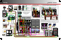
Positive Battery Cable Connections
CAUTION:
Equipment Damage
When connecting cables
from the Radian inverter
to the battery terminals,
make sure to observe
the proper polarity.
Connecting the cables
incorrectly can damage
or destroy the equipment
and void the product
warranty.
Ensure the mounting surface is strong enough to handle 3 times the total weight of all the components. Add plywood or other
reinforcing material as necessary to strengthen the surface.
Attach the wall bracket. Center the mounting holes on the wall studs. Use all 6 mounting screws to secure the bracket.
Lift the inverter so that the inverter bracket is above the wall bracket.
Lower the inverter so that the inverter bracket slips into the wall bracket.
If GSLC is not used: Secure the inverter to the surface using a minimum of 1 wall screw (or appropriate hardware).
If GSLC is used: Unscrew the inverter bottom screws approximately ¼” (0.6 cm) to 3/16" (0.5 cm).
Align the GSLC along the bottom of the inverter. Slide the bottom screws into the keyhole slots.
Mark the spots for the GSLC mounting feet. (If necessary, remove the GSLC to install wall anchors.) Install screws to secure the feet.
Follow the appropriate instructions for installing other components. Different mounting locations are available.
1
3
4
2
5
6
7
8
9
Keyhole Slots
1
2
3
4
5
6
7
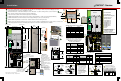
The FLEXmax charge
controller is mounted
with the FW-CCB bracket.
The FW-CCB2 allows two
controllers side by side (using
the forward holes to allow for
conduit.)
The Radian has two sets of
bracket positions. The GSLC
has one set.
NOTE: The FLEXmax
Extreme charge controller
attaches directly to the wall,
not the Radian system.
It does not use
OutBack brackets.
14.0"
(35.6 cm)
12.0"
(31.8 cm)
8
9
FN-DC
The Radian allows two locations
for the MATE3 mounting bracket
(FW-MB3).
The Radian has one
mounting location for the
HUB product. The GSLC
also has one location.
Left Side:
Right Side:
For GSLC door
clearance, space
systems 0.9"
(3.2 cm) apart.
When
stacking
multiple
inverters:
N
E
U
L1 L2
GRID
L1 L2
GEN
N
E
U
N
E
U
L1 L2
OUT
1
Wiring to AC terminals is
displayed on the Wiring page.
FN-DC wiring is displayed
on the Wiring page.
Bottom
Screws
19
Negative Battery Cable
Connections
Green
> 90% (blinks if charge parameters
are met)
Color
Red
Yellow
Yellow
Yellow ≥ 80%
≥ 70%
≥ 60%
≥ 60% off, < 60% solid, < 50% blinks
Battery State of Charge
FN-DC LED Indicators
Bolt 3/8"
DC
Positive
(+) Plate
Battery
Positive
(+) Lug
Flat
Washer
Nut
Lock
Washer
Flat
Washer
Shunt
Bolt 3/8"
Lock
Washer
Flat
Washer
Battery
Negative
(–) Lug
DC
Negative (-)
Plate
(GS-SBUS)
GSLC175-PV-120/240 GSLC175PV1-120/240
DC Disconnect
Stud
Battery
Positive
(+) Lug
FM80
Positive (+)
Terminal
Flat
Washer
Nut
Lock
Washer
FN-DC
Positive (+)
Sense
Terminal
4
22
20
20
!