
Outback Power GS4048A and GS8048A QuickStart Guide

Energize/Startup
Procedures
Pre-startup Procedures:
1. Double-check all wiring connections.
2. Inspect the enclosure to ensure no
debris or tools have been left inside.
3. Disconnect all AC loads at the backup
(or critical) load panel.
4. Disconnect the AC input feed to
the GSLC at the source.
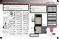
De-energize/Shutdown
Procedures
To de-energize or shut down the OutBack devices:
1. Turn off (open) the AC circuit breakers.
2. Turn off (open) the DC circuit breakers for the battery.
Wait 5 minutes for the devices to internally discharge themselves.
3. Turn off (open) the PV circuit breakers.
4. Turn off (open) the GFDI circuit breaker.
5. Verify 0 Vdc on the first DC bus of the inverter by placing the voltmeter
leads on and .
6. Verify 0 Vdc on the second DC bus by placing the voltmeter leads on
and .
7. Verify 0 Vdc on one PV circuit by placing the voltmeter leads on
and .
8. Verify 0 Vdc on the other PV circuit by placing the voltmeter leads on
and .
9. Verify 0 Vac on the AC output circuit breakers by placing the voltmeter
leads on and . Repeat this step for and .
900-0162-01-00 Rev A.vsd\Page-3\2014-01-24
©2014 OutBack Power Technologies. All Rights Reserved.
1
2
3
4
3a
3c
RADIAN Series
In 23.2 V 0.0 A
Out 27.6 V 0.0 A
0.000 kW 0.0 kWH
AUX: OFF Sleeping
In 23.2 V 0.0 A
Out 27.6 V 0.0 A
0.000 kW 0.0 kWH
AUX: OFF Sleeping
3a
3b
3c
1
2
3
4
WARNING: Lethal Voltage
Review the system configuration to identify all
possible sources of energy. Ensure ALL
sources of power are disconnected before
performing any installation or maintenance on
this equipment. Confirm that the terminals are
de-energized using a validated voltmeter
(rated for a minimum 1000 Vac and 1000 Vdc)
to verify the de-energized condition.
WARNING: Lethal Voltage
The numbered steps will remove power from
the inverter and charge controllers. However,
sources of energy may still be present inside
the GSLC and other locations. To ensure
absolute safety, disconnect ALL power
connections at the source.
1
1b
1c 1d
1b
1c
1b
1d
2c
2d
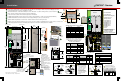
Test points 2c and 2d refer to the
right terminal of each circuit breaker.
2c
1b
2d
1b
WARNING: Burn Hazard
Internal parts can become hot
during operation. Do not
remove the cover during
operation or touch any internal
parts. Be sure to allow them
sufficient time to cool down
before attempting to perform any
maintenance.
Functional
Test Points
Battery Voltage Test Points
AC OUT Voltage Test Points
(Terminal bus bar = TBB)
PV Voltage Test Points
1a 1b 1c 1d
3a 3b 3c
3b
3c
2a 2b 2c 2d 1b
CAUTION: Fire Hazard
Before energizing, confirm that all hardware
is installed as shown on the Installation
page. Stacking battery terminal hardware in
any other order can overheat the terminals.
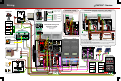
Functional
Test Points
Battery Voltage Test Points
GRID IN Voltage Test Points
(Terminal bus bar = TBB)
AC OUT Voltage Test Points
(Terminal bus bar = TBB)
PV Voltage Test Points
4a 3c4b
GEN IN Voltage Test Points
(Terminal bus bar = TBB)
In 23.2 V 0.0 A
Out 27.6 V 0.0 A
0.000 kW 0.0 kWH
AUX: OFF Sleeping
In 23.2 V 0.0 A
Out 27.6 V 0.0 A
0.000 kW 0.0 kWH
AUX: OFF Sleeping
1b
1a
1
2
3
4
5
3a
3b
3c
4a
4b
5a
5b
2b
6
6
2a
1a 1b
3a 3b 3c
5a 3c5b
2c2a 2b 2d 1b
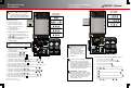
To energize or start the OutBack devices:
1. Using a digital voltmeter (DVM), verify 48 Vdc
on the DC input terminals by placing the DVM leads
on and .
Confirm that the battery voltage is correct for the
inverter and charge controller models.
Confirm the polarity.
2. Turn on (close) the GFDI circuit breaker.
3. Verify that the PV input for each charge controller
is in the correct range of open-circuit voltage and
confirm the polarity by:
a) placing the DVM leads on and , and
b) placing the DVM leads on and .
4. Turn on (close) the PV input circuit breakers.
5. Turn on (close) the DC circuit breakers from the battery bank to the inverter.
6. If the inverter is in the Off state, turn it On.
7. Verify 120 Vac on the AC Output L1 TBB by placing the DVM leads on and .
8. Verify 120 Vac on the AC Output L2 TBB and .
9. Verify 240 Vac between the AC Output TBBs by placing the DVM leads on and .
10. Turn on (close) the AC output circuit breakers.
11. Start the generator if appropriate. Verify 120/240 Vac on the terminals of the AC input sources.
12. Turn on the AC input feed to the GSLC at the source.
11. Verify 120 Vac on the GRID IN L1 TBB by placing the DVM leads on and .
12. Verify 120 Vac on the GRID IN L2 TBB and .
13. Verify 240 Vac between the GRID IN TBBs by placing the DVM leads on and .
14. Verify 120 Vac on the GEN IN L1 TBB by placing the DVM leads on and .
15. Verify 120 Vac on the GEN IN L2 TBB and .
16. Verify 240 Vac between the GEN IN TBBs by placing the DVM leads on and .
17. Turn on (close) the AC input circuit breakers.
18. Turn on the AC disconnects at the backup (or critical) load panel and test the loads.
1
2
3
4
5
3a 3c
3b 3c
3a 3b
4a 3c
4b 3c
5a
5b
3c
3c
4a 4b
5a 5b
1a 1b
6
CAUTION: Equipment Damage
Incorrect polarity will damage the equipment.
1b2a
1b2b
!
!