
Installation Manual User guide
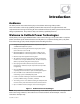
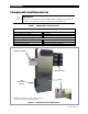
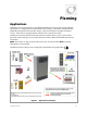

Table of Contents
2 900-0144-01-01 Rev A
List of Tables
Table 1 Components and Accessories ......................................................................................................... 4
Table 2 Battery Bank Elements ....................................................................................................................... 8
Table 3 Ground Conductor Size and Torque Requirements .............................................................. 19
Table 4 DC Conductor Size and Torque Requirements ....................................................................... 21
Table 5 AS4777.3 Acceptance Settings ..................................................................................................... 40
Table 6 Terms and Definitions ..................................................................................................................... 41
List of Figures
Figure 1 Radian Series Inverter/Charger .................................................................................................. 3
Figure 2 Radian Inverter and Components ............................................................................................. 4
Figure 3 Applications (Example) ................................................................................................................. 5
Figure 4 Bypass Switching .......................................................................................................................... 10
Figure 5 Bypass Switching for Multiple Inverters ............................................................................... 10
Figure 6 Inverter Dimensions .................................................................................................................... 11
Figure 7 System Dimensions ..................................................................................................................... 12
Figure 8 Installing the Mounting Plate ................................................................................................... 13
Figure 9 Mounting the Inverter ................................................................................................................ 14
Figure 10 Mounting for System Components ........................................................................................ 15
Figure 11 Removing the Front Cover ........................................................................................................ 16
Figure 12 DC Terminals, Ribbon Cables, and Auxiliary Terminals ................................................... 17
Figure 13 AC Terminals, Ports, and Ground Bus .................................................................................... 18
Figure 14 Chassis Ground TBB ..................................................................................................................... 19
Figure 15 GS7048E and GS3548E Battery Terminals ............................................................................ 20
Figure 16 DC Cable Hardware (Radian inverter) .................................................................................... 21
Figure 17 AC Terminals .................................................................................................................................. 22
Figure 18 AC Sources ...................................................................................................................................... 23
Figure 19 Accessory Connections .............................................................................................................. 24
Figure 20 ON/OFF Jumper and Connections.......................................................................................... 24
Figure 21 AUX Connections for Vent Fan (Example)............................................................................ 25
Figure 22 AUX Connections for Diversion (Example) .......................................................................... 26
Figure 23 Two-Wire Generator Start (RELAY AUX)................................................................................ 27
Figure 24 Two-Wire Generator Start (12V AUX) ..................................................................................... 27
Figure 25 Three-Wire Generator Start (Example) .................................................................................. 28
Figure 26 Single-Inverter AC System ......................................................................................................... 29
Figure 27 Single-Inverter AC Wiring with GS Load Center ................................................................. 30
Figure 28 OutBack Communications Manager and System Display .............................................. 31
Figure 29 Example of Parallel Stacking Arrangement (Three Inverters)........................................ 33
Figure 30 Parallel AC System ........................................................................................................................ 34
Figure 31 Parallel AC Wiring with GS Load Centers .............................................................................. 35
Figure 32 Example of Three-Phase Stacking (Three Inverters) ......................................................... 36
Figure 33 Example of Three-Phase Stacking (Nine Inverters) ........................................................... 36
Figure 34 Three-Phase AC System ............................................................................................................. 38
Figure 35 Three-Phase AC Wiring with GS Load Centers ................................................................... 39