
Installation Manual Instruction Manual
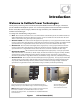
Introduction
900-0123-01-00 Rev B 7
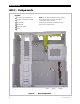
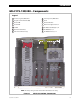
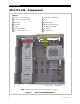
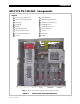
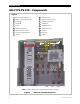
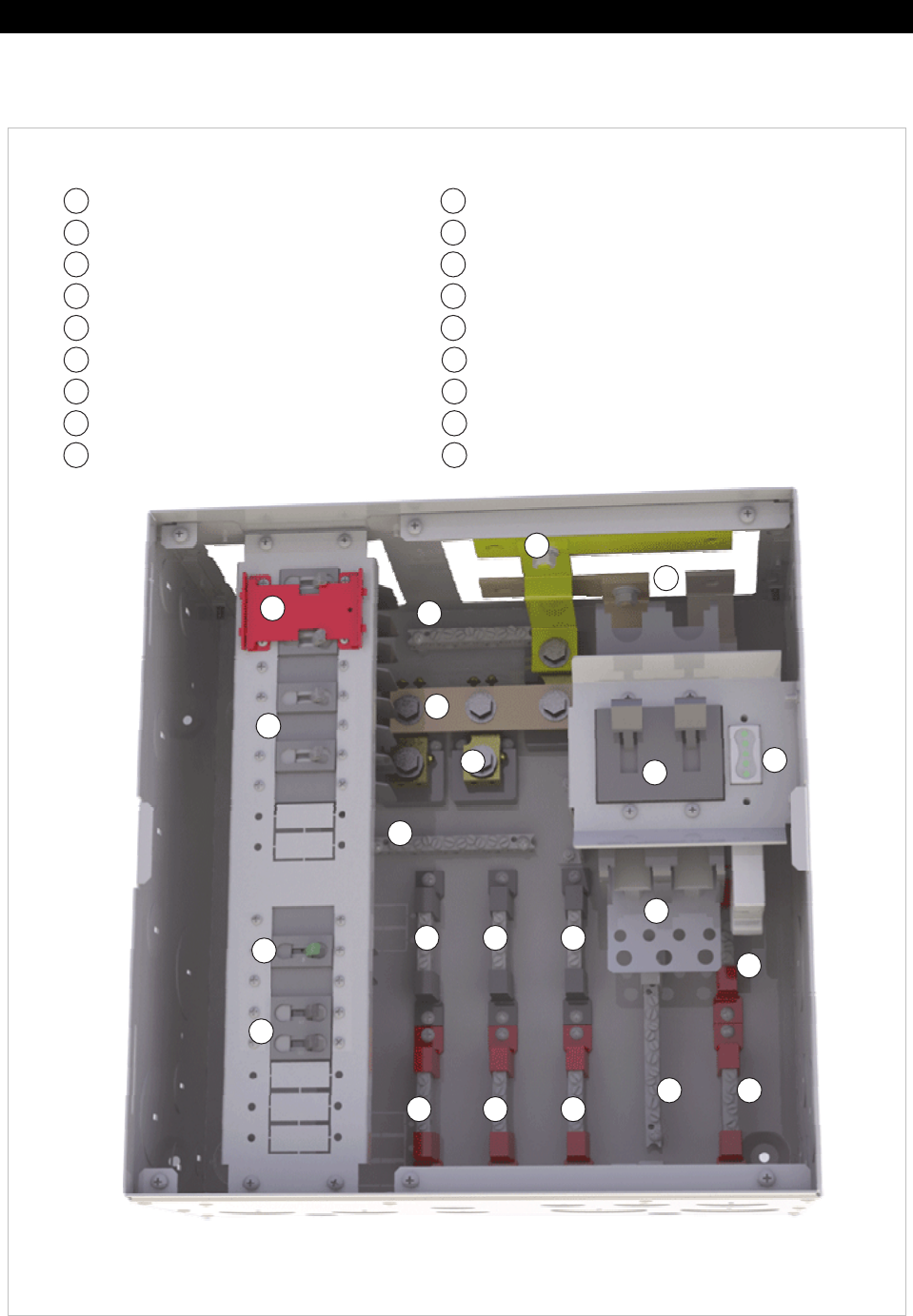
GSLC175-PV-120/240 – Components
Figure 5 GSLC175-PV-120/240 Components
Inverter (negative) DC Bus Bars
Negative Terminal Bus Bar (TBB)
Ground TBB
Neutral TBB
PV TBBs
DC Positive Cable Plate
Main Inverter Disconnect(s)
Inverter (positive) DC Bus Bars
Shunt(s)
Le
g
end
AC Circuit Breakers
Maintenance Bypass Interlock
AC TBBs (Inverter Output) L1, L2
AC TBBs (Grid) L1, L2
AC TBBs (Generator) L1, L2
PV Input Disconnects
Shunt Bus
FLEXnet DC
PV GFDI
NOTE: The factory wiring has been omitted from this illustration for clarity.
12
11
1
2
3
4
5
6
7
8
9
10
14
13
16
15
18
17
1
2
11
8
3
4 5
6
7
9
10
15
18
17
16
5
12
12
13
13 14
14