
Installation Manual Instruction Manual
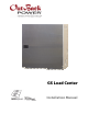
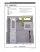
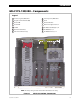
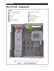
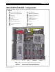
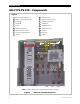

Table of Contents
2 900-0123-01-00 Rev B
List of Figures
Figure 1 GS Load Center (GSLC) ..................................................................................................................................3
Figure 2 GSLC Components..........................................................................................................................................4
Figure 3 GSLC175-120/240 Components ...............................................................................................................5
Figure 4 GSLC175-230 Components..........................................................................................................................6
Figure 5 GSLC175-PV-120/240 Components..........................................................................................................7
Figure 6 GSLC175-PV-230 Components...................................................................................................................8
Figure 7 Dimensions........................................................................................................................................................9
Figure 8 Knockouts and Mounting Holes for FLEXmax and HUB................................................................. 10
Figure 9 GSLC – Additional Components ............................................................................................................. 11
Figure 10 GSLC175-120/240 and GSLC175-230 – Additional Components ............................................... 11
Figure 11 Removing the Top Cover from the GSLC............................................................................................. 12
Figure 12 Removing the Front Door from the GSLC ...........................................................................................12
Figure 13 Removing the Interior Cover from the GSLC...................................................................................... 13
Figure 14 DC Positive Cable Plate .............................................................................................................................. 13
Figure 15 Assembling the DC Positive Cable Plate.............................................................................................. 14
Figure 16 Inverter Bus Bars ........................................................................................................................................... 15
Figure 17 Inverter Main Disconnects ........................................................................................................................ 16
Figure 18 DC Shunts........................................................................................................................................................ 17
Figure 19 Circuit Breakers ............................................................................................................................................. 18
Figure 20 Mounting the GSLC ..................................................................................................................................... 19
Figure 20 Mounting the GSLC (continued)
............................................................................................................. 20
Figure 21 Mounting the Charge Controller to the GSLC Enclosure............................................................... 21
Figure 22 Mounting the HUB to the GSLC Enclosure..........................................................................................22
Figure 23 Grounding....................................................................................................................................................... 23
Figure 24 Removing Bonding Connections............................................................................................................ 24
Figure 25 Battery Connections.................................................................................................................................... 25
Figure 26 FNDC and Wiring Block .............................................................................................................................. 26
Figure 27 Installing the FNDC...................................................................................................................................... 26
Figure 28 PV Connections in the GSLC..................................................................................................................... 28
Figure 29 PV Connections in the FLEXmax Charge Controller ........................................................................ 28
Figure 30 AC Terminal Bus Bars (split-phase)......................................................................................................... 29
Figure 31 Inverter AC Connections (split-phase).................................................................................................. 30
Figure 32 AC Terminal Bus Bars (single-phase) ..................................................................................................... 31
Figure 33 Inverter AC Connections (single-phase) .............................................................................................. 32
Figure 34 Maintenance Bypass Wiring (split-phase) ........................................................................................... 33
Figure 35 Maintenance Bypass Wiring (single-phase)........................................................................................34
Figure 36 Bypass Switches............................................................................................................................................ 35
Figure 37 OutBack Bypass (split-phase)................................................................................................................... 35
Figure 38 Bypass Switching for Multiple Inverters (split-phase)..................................................................... 36
Figure 39 Wiring Diagram – GSLC175-120/240..................................................................................................... 37
Figure 40 Wiring Diagram – GSLC175-PV-120/240 with FNDC ....................................................................... 38
Figure 41 Wiring Diagr
am – GSLC175-230.............................................................................................................. 39
Figure 42 Wiring Diagram – GSLC175-PV-230 with FNDC ................................................................................ 40